 Search on WeChat
 Technical Training1. Voltage Checking Method

The voltage checking method uses a voltmeter or multimeter on the AC voltage setting to measure live circuits, which is an effective method for locating fault points. The voltage checking method includes voltage step measurement and voltage segment measurement.
(1) Voltage Step Measurement
During measurement, first set the multimeter’s selector switch to the 500V AC voltage range, and then measure as shown in Figure 1.
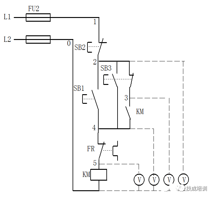
Figure 1 Voltage Step Measurement
Disconnect the main circuit and connect the control circuit power supply. If the contactor KM does not engage when the start button SB1 or SB3 is pressed, it indicates a fault in the control circuit.
During the test, two people need to cooperate. One person first measures the voltage between points 0 and 1 with the multimeter. If the voltage is 380V, it indicates that the power voltage of the control circuit is normal. Then, another person should press and hold SB1, while one person uses the black probe to connect to point 0 and the red probe to sequentially connect to points 2, 3, 4, and 5, measuring the voltage between 0-2, 0-3, 0-4, and 0-5, to determine the fault point based on the measurement results, see Table 1.
Table 1 Voltage Step Measurement Fault Point:
|
Fault Phenomenon |
Test Status |
0-2 |
0-3 |
0-4 |
0-5 |
Fault Point |
|
When pressing SB1 or SB3, KM does not engage |
Pressing SB1 |
0 380V 380V 380V 380V |
0 0 380V 380V 380V |
0 380V or 0 0 380V 380V |
0 380V or 0 0 0 380V |
SB2 normally closed contact poor connection SB3 normally closed contact poor connection SB1 contact poor connection FR normally closed contact poor connection KM coil circuit open |
(2) Voltage Segment Measurement
During measurement, set the multimeter’s selector switch to the 500V AC voltage range and measure as shown in Figure 2.
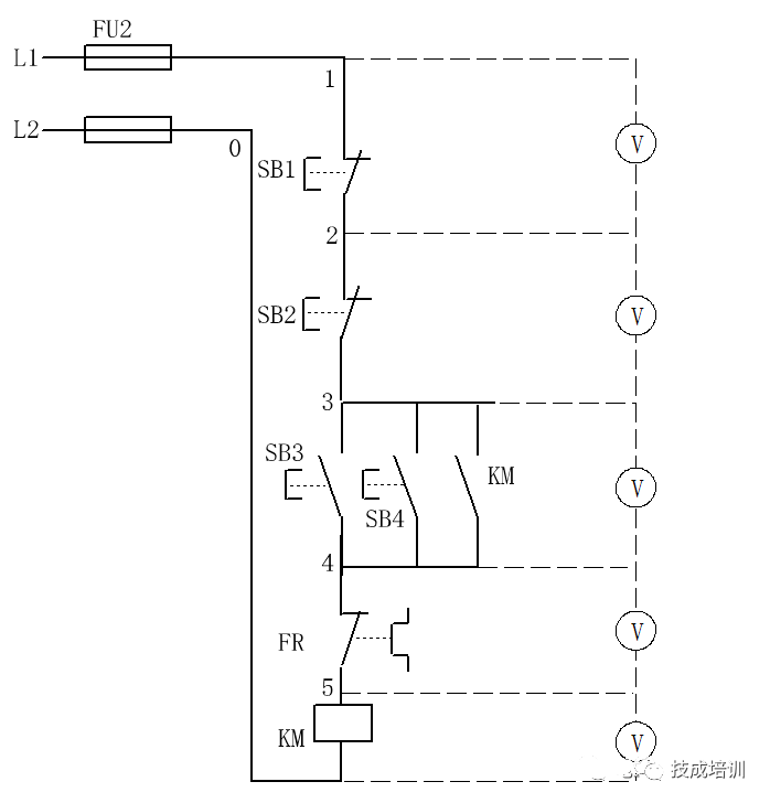
Figure 2 Voltage Segment Measurement
First, use the multimeter to measure the voltage between points 0 and 1. If the voltage is 380V, it indicates that the power voltage of the control circuit is normal. Then, one person should press and hold the start button SB3 or SB4. If the contactor KM does not engage, it indicates a fault in the control circuit. At this point, another person can use the red and black probes of the multimeter to measure the voltage between adjacent points 1-2, 2-3, 3-4, 4-5, and 5-0, and based on the measurement results, the fault point can be identified, see Table 2.
Table 2 Voltage Segment Measurement Values and Fault Points:
|
Fault Phenomenon |
Test Status |
1-2 |
2-3 |
3-4 |
4-5 |
5-0 |
Fault Point |
|
When pressing SB3 or SB4, KM does not engage |
Pressing SB3 or SB4 |
380V 0 0 0 0 |
0 380V 0 0 0 |
0 0 380V 0 0 |
0 0 0 380V 0 |
0 0 0 0 380V |
SB1 normally closed contact poor connection SB2 normally closed contact poor connection SB3 or SB4 normally open contact poor connection FR normally closed contact poor connection KM coil circuit open |
2. Resistance Checking Method
The resistance checking method uses the resistance setting of a multimeter to measure the circuit when it is powered off, which is a safe and effective method. The resistance checking method includes resistance step measurement and resistance segment measurement.
(1) Resistance Step Measurement
During measurement, first set the multimeter’s selector switch to the appropriate resistance range, then measure as shown in Figure 3.
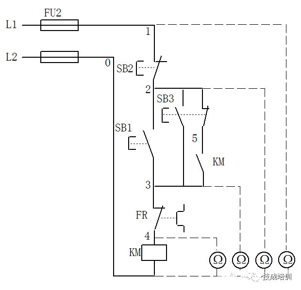
Figure 3 Resistance Step Measurement
Before measurement, first disconnect the main circuit power supply and connect the control circuit power supply. If the contactor KM does not engage when the start button SB1 or SB3 is pressed, it indicates a fault in the control circuit.
During detection, the control circuit power supply must be turned off (this is different from the voltage step measurement method), then one person should press and hold SB1 while another person uses the multimeter to measure the resistance values between points 0-1, 0-2, 0-3, and 0-4, and based on the measurement results, the fault point can be identified, see Table 3.
Table 3 Resistance Step Measurement Fault Points:
|
Fault Phenomenon |
Test Status |
0-1 |
0-2 |
0-3 |
0-4 |
Fault Point |
|
When pressing SB1 or SB3, KM does not engage |
Pressing SB1 |
∞ ∞ ∞ ∞ |
R ∞ ∞ ∞ |
R R ∞ ∞ |
R R R ∞ |
SB2 normally closed contact poor connection SB1 or SB3 normally open contact poor connection FR normally closed contact poor connection KM coil circuit open |
Note: R is the resistance value of the KM coil
(2) Resistance Segment Measurement
When measuring as shown in Figure 4, first disconnect the power supply, then one person should press and hold SB3 or SB4, while another person sets the multimeter’s selector switch to the appropriate resistance range and uses the red and black probes to measure the resistance between adjacent points 1-2, 2-3, 3-4, 4-5, and 5-0. If a very high resistance value (∞) is measured between any two points, it indicates poor connection or open circuit between those two points, see Table 4. The advantage of the resistance segment measurement method is safety, while the disadvantage is that inaccurate resistance values may lead to incorrect judgments, so the following points should be noted:
(1) When checking faults using the resistance segment measurement method, always disconnect the power supply first;
(2) If the measured circuit is in parallel with other circuits, the parallel circuit must be disconnected; otherwise, the measured resistance value will be inaccurate;
(3) When measuring high-resistance electrical components, set the multimeter’s resistance range to an appropriate level.
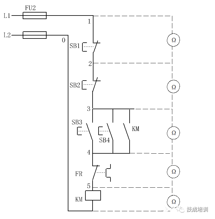
Figure 4 Resistance Segment Measurement
Table 4 Segment Measurement Resistance Values and Fault Points:
|
Fault Phenomenon |
Measurement Points |
Resistance Value |
Fault Point |
|
When pressing SB3 or SB4, KM does not engage |
1-2 2-3 3-4 4-5 5-0 |
∞ ∞ ∞ ∞ ∞ |
SB1 normally closed contact poor connection SB2 normally closed contact poor connection SB3 or SB4 normally open contact poor connection FR normally closed contact poor connection KM coil circuit open |
3. Short-Circuit Checking Method
Common faults in electrical equipment include open circuit faults, such as broken wires, loose connections, poor soldering, poor contact of contacts, and blown fuses. In addition to using voltage and resistance methods to check these faults, there is a simpler and more reliable method called the short-circuit method. When checking, use a well-insulated wire to short-circuit the suspected open circuit point; if the circuit is connected at a certain point, it indicates that the open circuit is at that point, as shown in Figure 5.
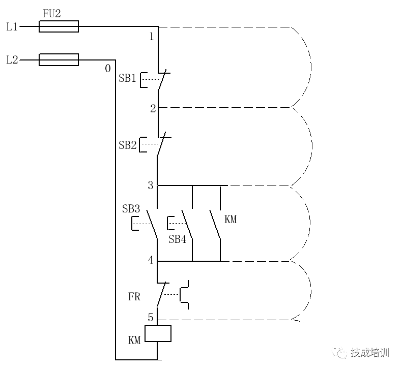
Figure 5 Short-Circuit Measurement Method
When using the short-circuit method to check faults, the following points must be noted:
☞ When using the short-circuit method, it involves live operation with insulated wires, so safety precautions must be taken to avoid electric shock accidents;
☞ The short-circuit method is only suitable for open circuit faults in wires and contacts with very small voltage drops; it cannot be used for appliances with larger voltage drops, such as resistors, coils, and windings, otherwise it may cause short-circuit faults;
☞ For critical parts of industrial machinery, the short-circuit method can only be used when it is ensured that no accidents will occur in the electrical or mechanical equipment.
Before using the short-circuit method, first measure the voltage between points 1-0 in Figure 5 with a multimeter. If the voltage is normal, one person can press and hold the start button SB3 or SB4, while another person uses a well-insulated wire to short-circuit the adjacent points 1-2, 2-3, 3-4, and 4-5 (be careful not to short-circuit points 5-0, as it will cause a short circuit). When short-circuiting at certain points, if the contactor KM engages, it indicates that the open circuit fault is between those two points, see Table 5.
Table 5 Fault Point Identification:
|
Fault Phenomenon |
Short-Circuit Point Label |
KM Action |
Fault Point |
|
When pressing SB3 or SB4, KM does not engage |
1-2 2-3 3-4 4-5 |
KM engages KM engages KM engages KM engages |
SB1 normally closed contact poor connection SB2 normally closed contact poor connection SB3 or SB4 normally open contact poor connection FR normally closed contact poor connection |
Disclaimer: This article is reproduced from the internet, and the copyright belongs to the original author. If there are any copyright issues, please contact us for deletion promptly. Thank you!
HISTORY/Previous Recommendations
Complete question bank for the 2021 electrician junior exam (including answers)
Three essential tools for electricians, easily accessible via WeChat!
[Bookmark] The “way out” for ten-year veteran electricians, the secret to earning over ten thousand a month!
Five major electrical drawing software (CAD, Eplan, CADe_simu…), which one do you choose?
Latest electrical CAD drawing software, with a super detailed installation tutorial!
Latest electrical drawing software EPLAN, with a super detailed installation tutorial!
Common problems for beginners using S7-200 SMART programming software (with download link)
Comprehensive electrical calculation EXCEL spreadsheets, automatically generated! No need to ask for electrical calculations!
Bluetooth headphones, electrician/PLC introductory books are free gifts? Come and get your electrical gifts!
Basic skills for PLC programming: Ladder diagrams and control circuits (with 1164 practical cases of Mitsubishi PLC)
Still can’t understand electrical diagrams? Basics of electrician drawing, simulation software available for quick theory and practice!
12 free electrician video courses, 10GB of software/e-books, and 30 days of free electrician live courses are available for free!
Don’t forget to like and share!