The issue of short circuits on circuit boards is frequently encountered in practical work. Some believe that only novice hardware engineers make mistakes with short circuits. This is not true; many experienced hardware engineers also face this problem. This issue is not only related to design but also closely tied to material quality and the production process. Therefore, it is essential to thoroughly review this topic.
01
Common Circuit Board Faults
Circuit boards often experience intermittent faults, which can include the following situations:
(1) Poor contact – Poor contact between the board and the slot, internal cable breakage, poor contact at wire plugs and terminals, and cold solder joints on components. To resolve such faults, carefully inspect suspected connectors for obvious oxidation or poor contact, scrape oxidized metal contact points, adjust the position of contact points, and test for good contact after re-plugging.
(2) Signal interference – For digital circuits, faults may only manifest under specific conditions. It may be due to excessive interference affecting the control system, or it could be that individual component parameters or overall performance parameters of the circuit board have changed, pushing the anti-interference capability to critical levels, thus causing faults. This type of fault requires checking whether the equipment is properly grounded, using a test pen to check if the equipment casing is live, or measuring the voltage between the equipment casing and the ground with a multimeter. Generally, this should be below 1V; if it exceeds 10V, grounding should be suspected.
(3) Poor thermal stability of components – Based on extensive practical experience, electrolytic capacitors are often the first culprits for poor thermal stability, followed by other capacitors, transistors, diodes, ICs, and resistors. This type of fault typically appears or disappears with the machine’s power-on time, essentially changing with the temperature of a faulty component. For instance, faults caused by aging electrolytic capacitors usually appear immediately upon power-up and disappear after some time, indicating a fault when cold and no fault when hot. The essence is that the capacitance of aging electrolytic capacitors changes with temperature; low temperatures result in smaller capacitance, causing poor filtering and preventing the circuit board from functioning normally. As power is applied for longer, the temperature of the electrolytic capacitor rises, capacitance increases, meeting filtering conditions, and the fault disappears. Thermal stability faults are considered soft faults, making it difficult to directly detect the faulty component during repairs. However, one can narrow down the inspection range by artificially heating or cooling suspected components using a hairdryer or heat gun, or cooling with a cotton swab dipped in alcohol. The condition of capacitors can be easily assessed using VI curve testing.
(4) Moisture and dust on the circuit board – Moisture and dust can conduct electricity, exhibiting a resistance effect. Moreover, during thermal expansion and contraction, the resistance value may change, which can affect other components, and if the effect is strong enough, it can alter circuit parameters, leading to faults. Such faults can be resolved by cleaning the circuit board. It is recommended to use board cleaning solution to wash the circuit board and thoroughly dry it with a hairdryer. Alcohol is not recommended as it can leave white residues on the board after cleaning.
(5) Software is also a factor to consider – Many parameters in the circuit are adjusted using software. If the margins for certain parameters are set too low and are near critical ranges, alarms will trigger when the machine operates under conditions that meet the software’s fault criteria. This type of fault can be resolved by adjusting the relevant parameters. For example, if the acceleration and deceleration times of a variable frequency drive are set improperly, an overcurrent or overload alarm may occur during operation; if CNC processing parameters are set incorrectly, the processed products may not meet requirements. In such cases, one should first suspect parameter setting issues and only after ruling out improper settings should one consider problems with the equipment itself.
02
Methods for Detecting Circuit Board Short Circuits
Short circuits are among the most common faults on circuit boards. There are generally two scenarios for short circuits: one is when the PCB has reached a certain service life, and the other is when the inspection during PCB production is inadequate. Short circuits can cause significant harm to PCBA, ranging from burning out components to total PCBA scrapping. So, what are the common types of circuit board short circuits? What methods are available for checking and preventing circuit board short circuits?
2.1 Types of Circuit Board Short Circuits
(1) Based on functionality: solder short circuits (e.g., solder bridges), PCB short circuits (e.g., residual copper, hole offset, etc.), internal layer micro short circuits, component short circuits, assembly short circuits, ESD/EOS breakdowns, electrochemical short circuits (e.g., chemical residues, electromigration), and other causes of short circuits.
(2) Based on wiring characteristics: line-to-line short circuits, line-to-surface (layer) short circuits, face-to-face (layer-to-layer) short circuits.
2.2 Methods to Avoid Circuit Board Short Circuits
(1) If there is a BGA chip on the circuit board, since the solder points are covered by the chip and are not visible, and it is a multi-layer board (more than four layers), it is best to separate the power supply for each chip during design using ferrite beads or 0-ohm resistors. This way, if a short circuit occurs between power and ground, disconnecting the ferrite bead (or resistor) makes it easy to locate the specific chip.
(2) Be particularly careful when soldering small surface mount capacitors, especially power filter capacitors (103 or 104), as their high quantity can easily lead to short circuits between power and ground. Sometimes, the capacitors themselves may be shorted, so the best approach is to test the capacitors before soldering.
(3) Develop good habits in manual soldering. Visually inspect the PCB before soldering and use a multimeter to check key circuits (especially power and ground) for short circuits; avoid swinging the soldering iron indiscriminately. If solder splashes onto the pins of the chip (especially for surface mount components), it can be difficult to trace. After soldering each chip, use a multimeter to check if power and ground are shorted.
2.3 Methods for Checking Circuit Board Short Circuits
(1) Open the PCB design diagram and light up the short circuit network to see which points are closest and most likely to connect. Pay special attention to internal short circuits within ICs.
(2) For single/double-layer boards with short circuit phenomena, cut the wires and power each functional block separately to progressively eliminate possibilities.
(3) Use a low-voltage (below 5V) high-current (3-5A) method for inspection. Generally, the heated area indicates the shorted component. However, this method poses certain dangers and is generally not recommended.
(4) To quickly locate the fault point, use a milliohm meter to measure the copper foil resistance on the circuit board. Due to the small resistance of copper foil, it is difficult to measure with an ordinary multimeter, but a milliohm meter can measure accurately. When measuring, place the probes across the leads of the shorted component to obtain the minimum resistance value.
(5) Use short circuit locating analysis instruments, which are more efficient and accurate for specific short circuit conditions. Common short circuit locating analysis instruments include the PROTEQCB2000 short circuit tracer from Singapore, the QT50 short circuit tracer from Hong Kong Lingzhi Technology, and the POLARToneOhm950 multi-layer board short circuit detection instrument from the UK.
03
The Necessity of Using Short Circuit Fault Detection Instruments
Let me share a personal experience. About eight or nine years ago, I designed a control board for an in-vehicle communication device, which used NXP’s T1020 and Broadcom’s BCM53115, both of which are BGA packaged chips. When the board was received, a static test showed a short circuit at 3.3V. It is known that a 3.3V short circuit is a situation that many engineers dread because 3.3V is related to almost all chips, making it very difficult to locate. At that time, I started checking from the power supply chip, and even after removing all the chips with a hot air gun, the 3.3V still showed a short circuit. Next, I began to check the decoupling capacitors under the BGA. Due to the large number of decoupling capacitors, it was impossible to test one at a time; I could only test small sections. Eventually, it was determined that a defective capacitor in a specific area caused the short circuit. In this case, the worst short circuit scenario occurred, although the probability was low, it still happened. This board took about two weeks to resolve, and the cost was indeed significant.
From the above review process, it can be seen that under normal conditions, there are no particularly effective means to resolve short circuit issues. Many boards are very costly, and discarding them entirely when problems arise would cause significant waste, so one can only rely on experience to check gradually. In the end, although the problem was solved, a huge price was paid. Below, I will focus on the troubleshooting methods of short circuit fault detection instruments, not to advertise a specific product, but to indicate that this is currently the most efficient method, as I have experienced the efficiency of such instruments.
04
Instruments for Detecting Circuit Board Short Circuits
Short circuit testers determine the presence of short circuit issues by measuring the current and voltage in the circuit and locating the specific short circuit position by changing the test points. The working principle of short circuit testers mainly includes the following steps:
(1) Current measurement – The short circuit tester inserts a certain resistance into the circuit and measures the current passing through that resistance to obtain the total current in the circuit. Current measurement can be achieved through inductive measurement, the Hall effect, or resistance measurement methods.
(2) Voltage measurement – A measuring resistor is added to the circuit, and the voltage across that resistor is measured to obtain the total voltage in the circuit. Voltage measurement can be conducted via the voltage divider principle using a voltmeter.
(3) Short circuit determination – The measurement results of current and voltage are compared. If the measured current significantly exceeds the current value corresponding to the voltage, it can be determined that there is a short circuit problem in the circuit.
(4) Short circuit localization – The short circuit tester can narrow down the range of the short circuit location by changing the test points, ultimately identifying the exact location of the short circuit.
Additionally, short circuit testers can also use the potential method for measurement. In this method, the excitation source outputs a constant current, and the voltage measuring probe measures the voltage at various points on the PCB to determine the short circuit point through comparison. When a short circuit occurs in the ground layer of a multi-layer PCB, the short circuit point can be identified by finding the high potential point.
Short circuit testers are widely used in the manufacturing of electronic devices, the power industry, and electrical engineering, helping to promptly eliminate faults and ensure the normal operation of circuits.
4.1 ToneOhm950 Short Circuit Tester
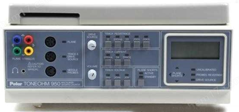
Figure 1 ToneOhm950 Short Circuit Tester
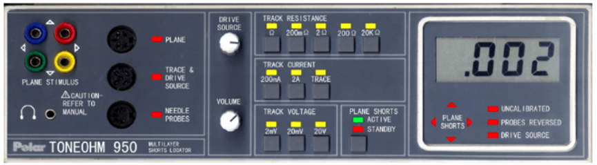
Figure 2 ToneOhm950 Short Circuit Tester Panel
4.1.1 Introduction
During the manufacturing and repair of circuit boards, problems with loads and line short circuits are commonly encountered. The causes of these faults can range from a small resistor short circuit (such as a solder bridge) to an entire microprocessor system failure caused by faulty devices on the bus.
Different forms of short circuits require different repair methods. The ToneOhm950 offers five different detection methods, allowing users to detect various forms of internal short circuits without needing to remove devices, cut copper tracks, or use other potentially damaging methods on the circuit board. The testing functions are as follows:
(1) Copper track resistance – micro-ohm meter function, used to detect low resistance short circuits;
(2) Copper track current – measures the direction of current on the copper track without needing to disconnect the circuit, suitable for bus or load variation issues;
(3) Current searching – does not require contact with the copper track, used for situations where the copper track or device is difficult to detect;
(4) Copper track voltage – measures the voltage drop caused by current flowing through the copper track, used in cases of very low resistance copper track load faults;
(5) Inter-layer short circuits – suitable for multi-layer boards, detecting short circuits between tracks and layers or between layers.
4.1.2 Low Resistance Short Circuit Application Example
Refer to Figure 3, where there is a short circuit point between the output of U1 and the input of U2. First, disconnect the power supply to the circuit board and place the probe at positions A and E. A reading and sound will be generated at the shorted copper track.
Moving the probe from A to B will produce a lower reading and a higher sound, indicating that the probe is getting closer to the short circuit point.
Moving the probe from B to C will produce a higher reading and a lower sound, indicating that the probe has moved past the short circuit point.
Thus, the short circuit point is between B and C.
Now, moving another probe from E will yield the lowest reading and the highest frequency sound. When the reading is about 15mΩ or lower, it indicates that the short circuit point is within a few millimeters of the two probes, and the sound will change to a chirping sound.
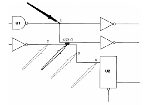
Figure 3 Short Circuit Fault Detection Diagram
4.2 TS980 Short Circuit Tracer
The TS980 short circuit tracer is a precision instrument designed for the electronic industry to eliminate short circuit issues easily.
(1) Uses non-destructive measurement methods without disassembling components or cutting copper foil, thus avoiding damage to the PCB;
(2) Generates a very small excitation signal, which will not damage components;
(3) Offers two complementary detection methods.
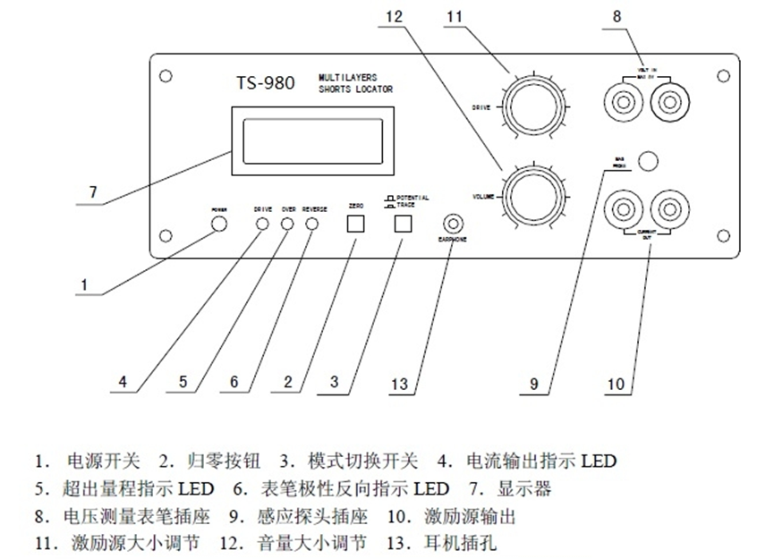
Figure 4 Instrument Panel
4.2.1 Working Principle:
The instrument consists mainly of an excitation source, voltage channel, and current sensing channel, as shown in Figure 5.
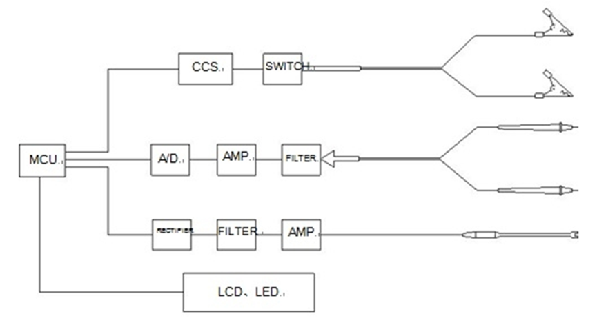
Figure 5 TS980 Composition
4.2.1.1 Potential Measurement Method
When the mode button pops up, the short circuit tracer operates in the potential measurement mode. The excitation source outputs a constant current, and the voltage measuring probe measures the voltage at various points on the PCB to determine the short circuit point, similar to measuring potential lines in an electric field, hence the name potential measurement method. When a short circuit occurs in the ground layer of a multi-layer PCB, the short circuit point can be identified by finding the highest potential point. As shown in Figure 6, the current disperses across the copper foil, creating equipotential lines. The potential at the current entry point is the highest. By using the potential method to find this highest potential point, the current’s entry point into this layer of copper foil can be identified, making it easy to locate the short circuit point.
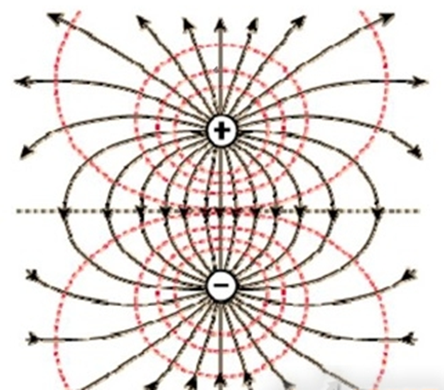
Figure 6 Equipotential Line
The excitation source part of the TS980 short circuit tracer is electrically isolated from other parts, allowing any two points to be selected for measuring the voltage difference.
The TS980 short circuit tracer has a zeroing button that sets any measured voltage as the zero voltage point, allowing measurements of other parts of the PCB to yield an intuitive voltage difference. This comparative method supports negative voltage display, but only as a relative negative voltage. If the voltage at the potential measuring probe is less than 0V, the instrument will indicate that the probe’s polarity is reversed. Pressing the zero button will remove the current value (similar to the “tare” function of electronic scales), and the display will show corresponding information. Pressing the zero button again restores the previous value without performing a tare action.
The voltage displayed by the TS980 short circuit tracer is in microvolts, with an excitation current of 100mA, and the maximum range is 2V.
Figure 7 illustrates the potential measurement method, where the excitation source is connected across the shorted network, and the probe searches for the highest potential point in the ground layer. The black point indicates the short circuit point, where the highest potential is observed.
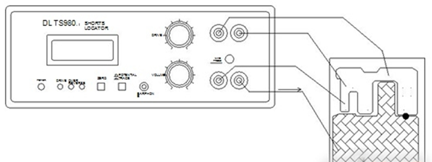
Figure 7 Potential Measurement Method Diagram
4.2.1.2 Current Sensing Method
The excitation source outputs a processed excitation current signal, and the probe detects the magnetic field generated by the current. The stronger the current, the stronger the magnetic field, and the stronger the signal detected by the probe, resulting in a frequency and sound corresponding to the signal. The stronger the signal, the higher the frequency of the sound emitted by the speaker; conversely, a weaker signal results in a lower frequency sound until there is no sound.
The signal obtained from the probe corresponds to the tone emitted by the speaker, which is closely related to the size of the detected current and the distance between the probe and the measurement point. Under the same conditions, if the distance from the probe to the measured point differs by 1mm, the speaker will emit noticeably different sounds.
The instrument has an excitation source adjustment knob that can be set from 10mA to 100mA. The volume of the speaker can also be adjusted with a volume control knob, and plugging in headphones cuts off the speaker output, directing the signal to the headphones.
The current sensing probe used has a certain directionality; please perform two detections, rotating the probe 90° in between.
4.2.2 Example Explanation: Power to Ground Short Circuit
Connect one end of the excitation source to the power terminal and the other end to the ground line (be careful not to reverse the polarity) to apply a constant current to the shorted section. Generally, the ground network on the circuit board is densely distributed, so connect the low voltage end of the resistance detection probe (black probe) to the ground of the excitation signal and use the red probe to detect other ground networks (such as the negative terminal of the power filter electrolytic capacitor). Different locations will show varying voltages until the highest voltage point is found. This point also has a characteristic: the voltage around it in the ground network significantly decreases in one direction. With these two characteristics, the short circuit point is located. Additionally, using the current sensing method to detect internal current in suspect components is also a quick way to find the short circuit point.
4.2.3 Instrument Specifications
(1) Power Input
a) AC 220V ±10%, 50Hz or 60Hz;
b) Maximum current 0.2A.
(2) Potential Measurement (at room temperature 20℃ ±5℃)
a) Display digits six and a half, with ranges of 20 and 1;
b) Excitation current 100mA, daily stability 20ppm;
c) Maximum output voltage 5V under no load, maximum output voltage 2.5V under full load, equivalent detectable resistance value 25Ω;
d) Maximum output power 0.25W;
e) Low-frequency equivalent noise of current output maximum 1uA (peak-to-peak value);
f) Annual accuracy of voltage measurement 70ppm;
g) Noise of voltage measurement channel below 0.1uV (0.1-10Hz peak-to-peak value);
h) Resolution of 10uΩ and 1uΩ (when measuring resistance);
i) 50Hz power frequency suppression better than -80dB;
j) Signal suppression capability above 1kHz better than -80dB;
k) Voltage sampling period 285ms.
(3) Current Tracking
a) Sensitivity Δf/ΔB better than 50Hz/0.01Gs;
b) Excitation current adjustment range 100-10mA;
c) 50Hz power frequency suppression better than -40dB;
d) Signal suppression capability above 1kHz better than -80dB.
(4) Dimensions: 205mm × 200mm × 85mm (L × W × H).
(5) Weight: 4.3kg.
05
Conclusion
For circuit boards, short circuits are the most serious faults. If not resolved, the circuit board can only be discarded or scrapped. For circuit boards in the R&D process, as the number of prototypes is small, generally, only one board in a batch will experience a short circuit fault. Resolving this through conventional means is still bearable in terms of cost. However, for mass production, if a batch of circuit boards consists of hundreds or thousands of units, even a small probability of short circuit faults can lead to an enormous workload to address each one individually. At this point, the value of short circuit detection instruments becomes fully apparent. Although short circuit detectors are not a new concept, having begun appearing in China over a decade ago, they still remain scarce in most companies and research institutions. The main reason is that previously imported equipment was too expensive and not widely useful. With the rise of domestic testing equipment in recent years, more and more domestic brands of short circuit detectors have emerged, and prices have dropped significantly. On the other hand, as the functionality of circuit boards becomes increasingly complex and costs rise, short circuit issues become more challenging to locate. Therefore, the promotion of short circuit detection instruments comes at a timely moment.

The Hardware Engineer Practical Training Camp is a knowledge-sharing platform created by the author aimed at hardware beginners, designed to help novices quickly grow into qualified hardware engineers. Everyone is welcome to join, learn, and progress together.