CAN Communication: The Unsung Hero of Enhanced Device Collaboration Efficiency
1. The Importance of CAN Communication
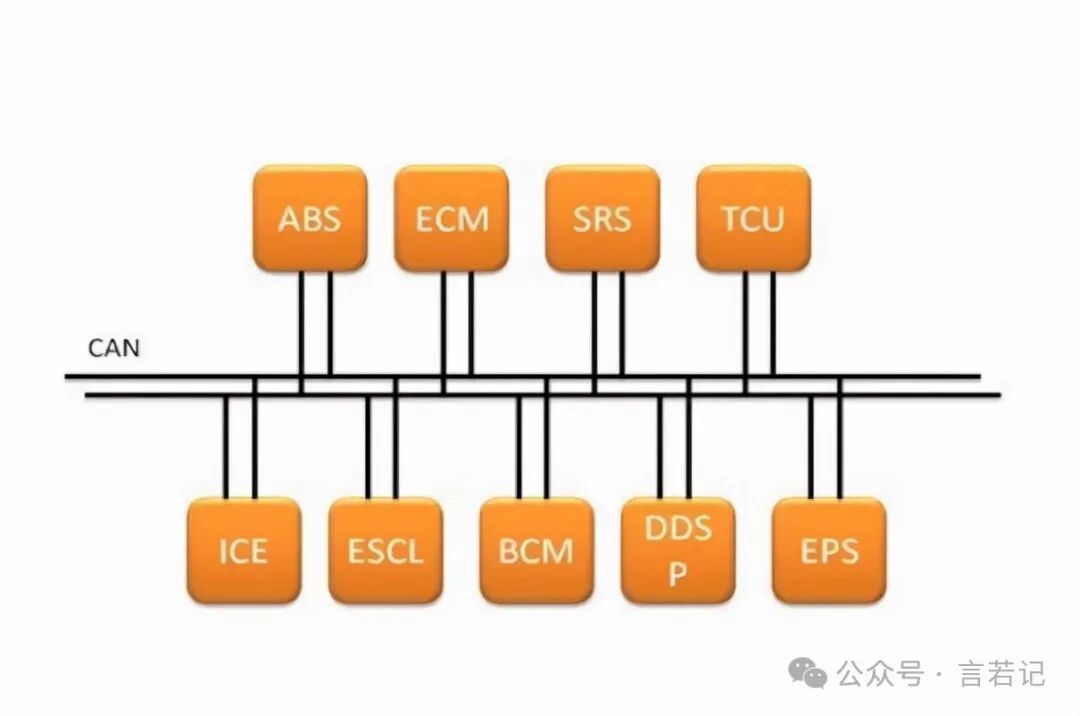
CAN (Controller Area Network) is a communication protocol widely used in automotive, industrial automation, and other high-performance systems. Originally developed by Bosch in the 1980s for the automotive industry, it quickly became the backbone of modern vehicle communication systems. The CAN bus allows multiple electronic control units (ECUs) within a vehicle to exchange data in real-time, enhancing the vehicle’s performance, efficiency, and safety. For example, in a car, the brake signal can be quickly transmitted via the CAN bus to the brake lights and other control systems, ensuring safe operation of the vehicle.
CAN communication is not only crucial in the automotive field but also plays a significant role in industrial applications. In industrial automation, the CAN bus improves machine collaboration efficiency by simplifying communication between devices, ensuring smooth operation of production lines. The robustness, reliability, and resistance to electromagnetic interference of the CAN bus make it an ideal communication solution in various harsh environments, such as factories with high noise interference, where it ensures the accuracy of data transmission.
2. Basic Concepts of CAN Communication
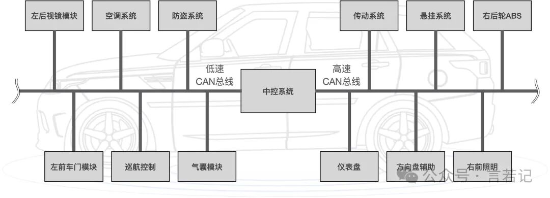 What is CAN?
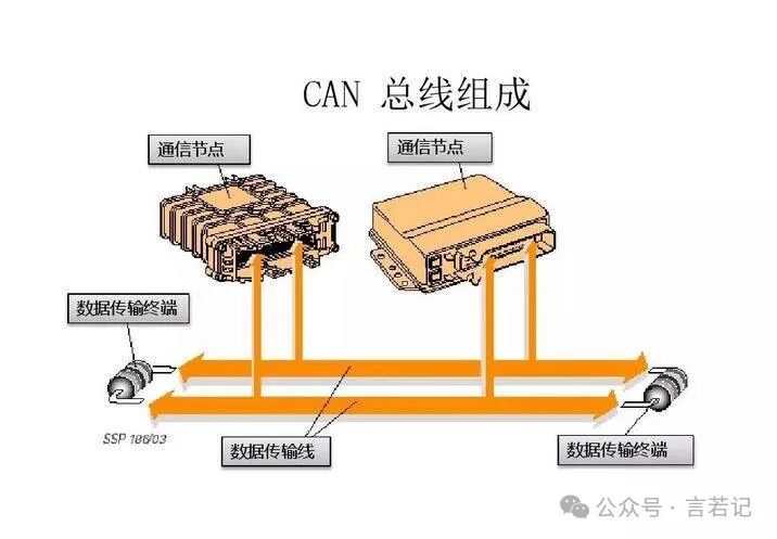
CAN (Controller Area Network) is a protocol that facilitates communication between multiple devices. You can think of it as a “chat tool” for devices, connecting them with a “bus” line, allowing them to “talk” to each other. This bus structure significantly reduces wiring complexity, especially useful in cars and factories.
What is the bus structure?
The communication method of the CAN bus is similar to queuing for a phone call. In this network, all devices (nodes) are connected to the same line; whoever needs to send a message broadcasts on the “bus,” while other nodes listen to who is speaking. This method reduces the number of wires and costs. For instance, if each device had to connect individually to every other device, the wiring in a car would be chaotic, but with CAN, the bus acts like a shared chat channel where everyone speaks as needed.
Multi-master Communication and Priority Mechanism
Unlike everyday communication tools where everyone speaks at once, CAN is orderly; the more important the message, the higher the priority to speak. This is achieved through a “priority” mechanism—each message has an “ID,” and the smaller the ID number, the higher the priority. When multiple devices send messages simultaneously, the higher priority message will “interrupt” the lower priority messages and be sent first, while lower priority messages will wait. This is similar to a team discussion where urgent messages receive priority attention and handling.。
Frame Structure: The “Message Format” of CAN Communication
In CAN communication, messages are transmitted through a structure called a “frame.” You can think of a frame as the “message” sent between devices. Each CAN frame contains various information to ensure effective message delivery, identification, and error detection.
1. ID Number (Identifier)
The first important part of the frame is the ID number, also known as the identifier. Its role is to determine the priority of this message in communication. On the CAN bus, multiple devices (nodes) can send messages simultaneously, but higher priority messages will “interrupt” lower priority messages and be sent first. Therefore, the smaller the ID number, the higher the priority.。
For example, if both the brake signal and the status of the air conditioning in a car need to send messages, the brake signal should obviously have a higher priority because it is directly related to safety. Therefore, the ID number of the brake signal will be smaller than that of the air conditioning message, ensuring it is transmitted first.
2. Data Field
This is the core part of the frame, containing the actual data being transmitted. The length of the data field can range from 0 bytes to 8 bytes, depending on the amount of information to be conveyed. For example, temperature data from a sensor may only require a few bytes, while more complex control information may require more bytes.
In a car, sensors can send the current engine speed data via the CAN bus, and the data field will contain the specific value collected by this sensor, such as “3000 RPM.” The receiving device can use this data to issue further control commands, such as adjusting the fuel injection amount, etc.。
3. Checksum (CRC)
The checksum (Cyclic Redundancy Check, CRC) is an important part of ensuring the accuracy of data transmission. During message transmission, data may be affected by electromagnetic interference or other factors, leading to errors. CRC is a mathematical operation that can detect whether the data has been tampered with or corrupted during transmission. The sending device generates a CRC code when sending a message, and the receiving device performs the same calculation on the received message to ensure the CRC codes match, guaranteeing data correctness.。
If a CAN message changes during transmission due to interference, such as a bit being flipped incorrectly, the CRC code calculated by the receiving device will not match the CRC code from the sending device, at which point the receiving device will discard this message and request a retransmission, ensuring the reliability of communication.
3. Hierarchical Structure of the CAN Protocol
Physical Layer
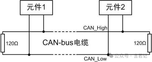
The physical layer is the foundation of the CAN protocol, defining the actual signal transmission method, which includes electrical characteristics and transmission medium. In the CAN bus, data is transmitted via a pair of twisted wires, using differential signaling to enhance resistance to electromagnetic interference.
-
Twisted Pair Structure: The two wires of the CAN bus are called CAN_H and CAN_L, and data is transmitted through them in the form of differential signals. The advantage of differential signaling is that when the voltage difference between CAN_H and CAN_L is at a specific value, it can effectively resist external electromagnetic interference.。
-
Voltage Logic: The CAN protocol uses dominant and recessive logic to represent binary data. When the voltage difference between CAN_H and CAN_L is 2V, it indicates a dominant state, or logic “0”; when the voltage difference is 0, it indicates a recessive state, or logic “1”. This way, CAN ensures stable signal transmission in noisy environments.。
Data Link Layer
The data link layer handles the format of the data, frame structure, error detection, and arbitration mechanisms. It can be further divided into logical link control and medium access control (MAC) sublayers.
-
Frame Format: CAN data is transmitted through frames, which are divided into standard frames and extended frames. The ID number of a standard frame is 11 bits, while that of an extended frame is 29 bits. The frame includes the message ID, data field, checksum (CRC), arbitration bit, and acknowledgment bit.。
-
Arbitration Mechanism: CAN uses a non-destructive arbitration mechanism. Multiple nodes can attempt to send messages simultaneously, but priority is determined by comparing ID numbers. Higher priority messages occupy the bus, while lower priority nodes yield and wait. This mechanism ensures real-time performance, especially in scenarios requiring urgent responses, such as automotive control.。
-
Error Detection and Recovery: The CAN bus has powerful error detection capabilities, including bit errors, stuffing errors, CRC errors, etc. Whenever an error is detected, the system sends an error frame and automatically retransmits. This mechanism ensures the reliability of data transmission.。
4. Error Detection and Recovery Mechanisms of CAN
The error detection and recovery mechanisms of the CAN communication system are crucial for its high reliability. It employs various methods to ensure the accuracy and stability of data transmission, even in noisy environments. These mechanisms include five main error detection methods and automatic recovery mechanisms.
 Error Detection
1. Bit Error
A bit error occurs when a node detects that the data it sent does not match the data actually transmitted on the bus. On the CAN bus, nodes send and listen to data simultaneously. If a node sends a dominant bit (logic 0) but detects a recessive bit (logic 1), it will recognize this as a bit error.。 When a node detects a bit error, it immediately sends an error frame to inform other nodes of the transmission failure and then attempts to retransmit the data.
2. Stuffing Error
The CAN protocol stipulates that during message transmission, if there are 5 consecutive identical bits (whether logic 0 or logic 1), the system will automatically insert a complementary bit, called a stuffing bit, to avoid prolonged constant levels that could cause the bus to fail. If 6 consecutive identical bits are found after these inserted bits, a stuffing error occurs, indicating a transmission error.。
3. CRC Error
The CRC checksum is key to ensuring data transmission integrity. Each CAN message is sent with a CRC checksum. The receiving node verifies the data’s correctness by recalculating the CRC code. If the calculated CRC code does not match the received CRC code, the system detects a CRC error. At this point, the receiving node will discard the message and request a retransmission.。
4. Acknowledgment Error
The acknowledgment mechanism of the CAN protocol ensures that messages are successfully received. When the sending node sends a message, it expects at least one receiving node to return an acknowledgment signal upon successful reception. If no acknowledgment is received, the sending node will consider it an acknowledgment error and retransmit the message.。
5. Format Error
A format error occurs when a node detects a sequence of bits that does not conform to the protocol format at a fixed position. Different parts of a CAN frame have strict format requirements, such as start bits, control fields, and termination fields. If a node finds that these parts do not conform to the specified format, it will issue a format error.。
Automatic Recovery Mechanism
CAN not only detects errors but also has an automatic recovery function. Upon detecting an error, devices on the CAN network will send an error frame to notify other nodes of the issue. The erroneous node will temporarily stop sending messages and wait for the self-recovery process to complete. Each node in the CAN system has an error counter to track transmission and reception errors. When a node’s error counter exceeds a certain threshold, it will enter a passive error state or even a bus-off state to avoid further interference with the network.。
5. Practical Applications of CAN
1. Automotive Industry
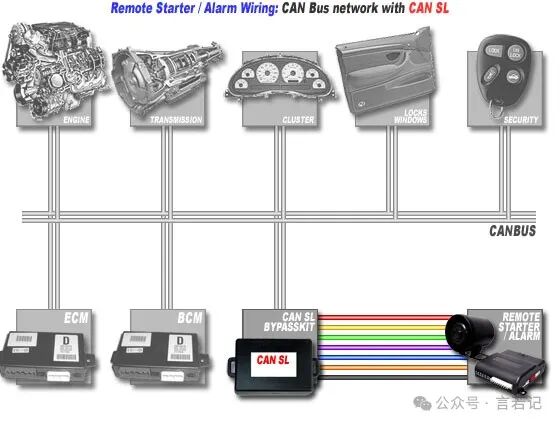
The automotive industry is the earliest and most widespread application field of the CAN protocol. In modern vehicles, multiple electronic control units (ECUs) communicate with each other via the CAN bus to manage and coordinate various systems of the vehicle, such as engine management, transmission control, braking systems, and in-car entertainment systems. Specifically, here are several common application scenarios:
-
Engine Control: The engine control unit obtains sensor data such as throttle position, temperature, and oxygen sensor via the CAN bus to adjust fuel injection and ignition timing, ensuring efficient engine operation.
-
ABS System: The ABS (Anti-lock Braking System) obtains real-time speed information from each wheel via the CAN bus to determine whether to activate the braking system, preventing loss of control during emergency braking.。
-
Body Control: Functions such as lighting control, window raising and lowering, and electric seat adjustment in the car also rely on the CAN bus for data transmission, achieving synchronized operation among multiple devices.
Industrial Automation
The application of the CAN protocol in the industrial field is mainly reflected in machine control and factory automation. In industrial environments, devices need to achieve high-speed, stable data communication, and the CAN bus, with its resistance to electromagnetic interference and strong real-time performance, becomes the ideal choice for communication between sensors, actuators, and controllers.
-
Machine Control: In automated production lines, CAN is used to control different devices and machines, such as robotic arms, conveyor belts, and CNC machine tools. Through the CAN bus, various devices can work synchronously, ensuring efficient operation of the production line.。
-
Distributed Control Systems (DCS): CAN is used for data transmission between multiple control units in DCS to achieve distributed control. Each unit sends and receives sensor data via the CAN bus to implement control commands, thereby enhancing the flexibility and scalability of the system.。
Smart Home and Transportation
In the smart home sector, the CAN bus is used to connect various devices in the home, such as lighting, air conditioning, and security systems. Through the CAN bus, different devices in the home can communicate with each other, achieving automated control. For example, when you open the door, the CAN bus can simultaneously control the lighting and heating, making the home environment smarter and more convenient.。
In the smart transportation sector, CAN is used for communication in onboard systems of public transport vehicles such as buses and subways. The door control system, passenger information display, and even onboard monitoring devices of buses can communicate with each other via the CAN bus, ensuring the normal operation of the transport vehicles. For example, the driving system of a bus sends door opening and closing signals via CAN and synchronously updates passenger information on the display inside the vehicle.。
END
 Scan to follow and interact to learn more knowledge