CAN Bus to DeviceNet—ADFweb Gateway Converter– Guangzhou Xinyu IoT
Author: Zou Wuyi Mobile185-020-77899 Email: [email protected]
1 Features: The CAN Bus to DeviceNet gateway has the following features:
- Realizes bidirectional information transmission between the CAN bus and DeviceNet network;
- Provides electrical isolation between the two buses;
- Can read CAN bus frames from DeviceNet frames;
- Can write CAN bus frames to DeviceNet frames;
- Operating temperature range is -30°C to 70°C.
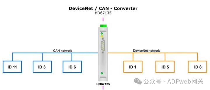
- “Gateway CAN Bus – DeviceNet Converter” enables communication between the CAN bus network and DeviceNet network.
To perform the following operations on your computer, you need to install Compositor SW67135 software:
- Define reading CAN bus frames from DeviceNet;
- Define writing CAN bus frames to DeviceNet.
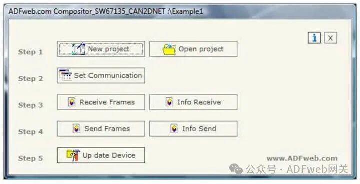
2 New Project / Open Project: Click“ New Project” button to create a folder that contains the configuration information for the entire device. Device configuration information can also be imported or exported:
- To clone the configuration information of a programmable CANopen to DeviceNet gateway for configuring another device in the same way, you must keep the folder and all its contents;
- To clone a project for a different version of that project, simply copy the project folder and rename it, then click“ Open Project” button to open the new folder. When creating a new project or opening an existing project, you will have access to various configuration sections of the software:
- “Set Communication”;
- “Receive Frame”;
- “Send Frame”;
3 Communication Settings
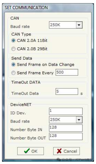
This section defines the basic communication parameters for the two buses (CANopen and DeviceNet).
In the main window of SW67135, click the“Set Communication” button (as shown in Figure 2) to pop up the“SET COMMUNICATION” window (as shown in Figure 3).
“CAN” Field Meanings:
- In the“ Baud Rate” field, you can define the baud rate of the CAN bus;
- In the“CAN Type” field, you can select the type of CAN bus (CAN 2.0A 11 bit or CAN 2.0B 29 bit);
- If you check the“ Send Frame on Data Change” field, a frame will be sent when the data changes; otherwise, if you check the“ Send Frame Every xx Milliseconds” field, a frame will be sent after the time you enter in that field as defined in the“Send Frame” table;
- In the“ Data Timeout” field, enter a time value; when the time exceeds and the data is no longer reliable, the data will be set to 0x00. By checking the delete option in the“Receive Frame” section, this feature can be enabled for each received CAN frame.
“DeviceNet” Field Meanings:
- In the“ Device ID” field, you can define the gateway address for DeviceNet;
- In the“ Baud Rate” field, you can define the baud rate for DeviceNet;
- In the“ Input Byte Count” field, define the number of bytes from DeviceNet to the gateway (up to 128 bytes);
- In the“ Output Byte Count” field, define the number of bytes from the gateway to DeviceNet (up to 128 bytes).
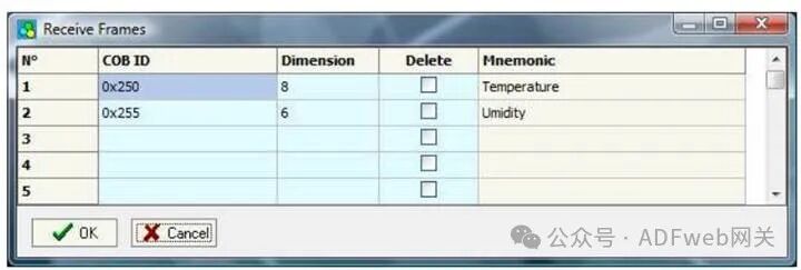
4 Receive Frame: In the main window (for SW67135, as shown in Figure 2), press the“ Receive Frame” button, and the“ Receive Frame” window will pop up (as shown in Figure 4). The COB inserted in this table is the data read from DeviceNet. The meanings of each column of data are as follows:
- In the“COB ID” field, insert the COB of the CAN bus frame;
- In the“Size” field, insert the number of bytes of the COB;
- If the“ Delete” field is checked, the data in the frame will be erased after the“ Timeout Data” expires;
- In the“Mnemonic” field, you can insert a brief description.
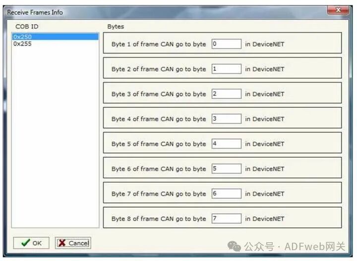
5 Information Reception: In the SW67135 main window (Figure 2), press the“ Information Reception” button, and the“ Receive Frame Information” window will pop up (Figure 5).
- In the“COB ID” field, the COB ID you entered in the“ Receive Frame” window will be displayed;
- In the“ Bytes” field, select the corresponding relationship with the bytes in DeviceNet. For example: The first byte of the CAN frame can correspond to the 0 byte in DeviceNet. For instance, if the first byte of the CAN frame is 0x11, then the 0x11 will be read in the 0 byte of DeviceNet.