Introduction
But it doesn’t matter if you don’t know; after seeing the pictures, you will be intrigued!
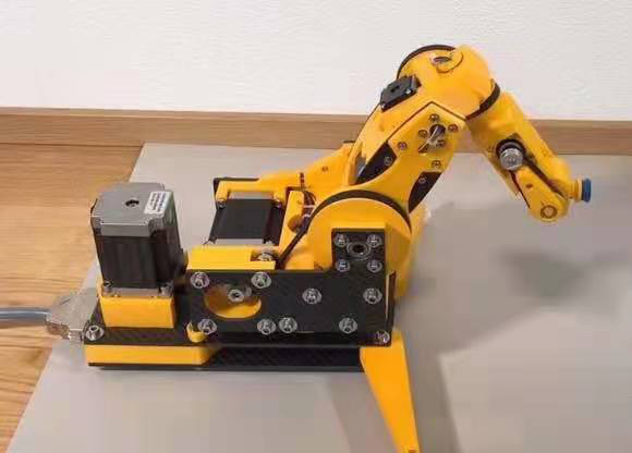
It looks like a pretty cool desktop-level robotic arm, and it’s a stepper motor arm. This robotic arm can compete with the Anno robotic arm from GuYue, so you know what I mean~
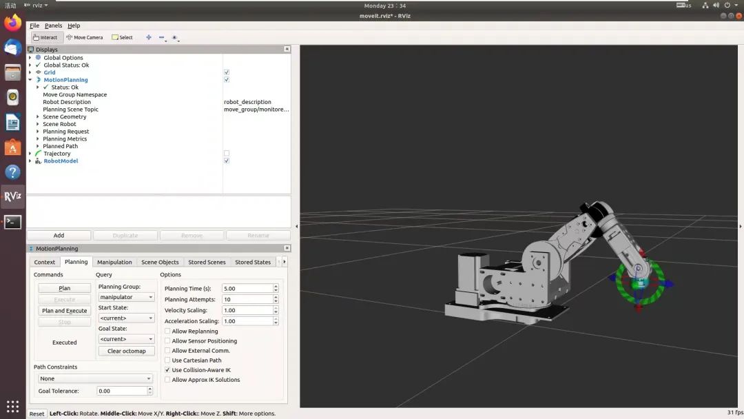
Without further ado, let’s take a look at the results!
The effect looks quite nice! The model function package here is based on the materials from the great XueMing, and you can find relevant course content at GuYue Academy. This course is free~ (https://class.guyuehome.com/detail/p_5faa57f1e4b04db7c08da8f8/6)
Of course, I am not just here to play with the simulation; if we are going to do it, let’s do it big, roll up our sleeves and get to work!
Please ignore this pile of flying wires, and don’t ask me why the video is from Kuaishou; after all, I have limited skills and can’t handle video editing~
Manufacturing the Robotic Arm
Let’s start building the SmallArmRobot robotic arm!
To build this robotic arm, we first need the physical parts. The model of this robotic arm can be downloaded online. Here, I provide a download link from Baidu Cloud.
Link:
https://pan.baidu.com/s/1nIB4dy-eBiX7VpYNtvFQFA
You can use 3D printing to create this robotic arm after downloading it, and you will also need to prepare a large number of screws and tools, as well as six stepper motors: 2 of 57 stepper motors, 1 of 42 stepper motor, 2 of 28 stepper motors, and 1 of 20 stepper motor. The assembly tutorial and related BOM list are all provided in the link.
Of course, you can also take the easy route and purchase a physical robotic arm directly from Xianyu; the current price is around 600 to 800. You only need the main body of the robotic arm; I redesigned the driver board (the one provided by the open-source community is a bit difficult to use). Those who have the conditions can replace the side and bottom plates with stainless steel, which not only looks cooler but also increases weight and stability. Some experts have done this, and I am quite envious~
In any case, the goal is to get a physical robotic arm out there! The cost of the SmallArmRobot robotic arm is relatively manageable, considering the six stepper motors involved and the numerous 3D printed parts~
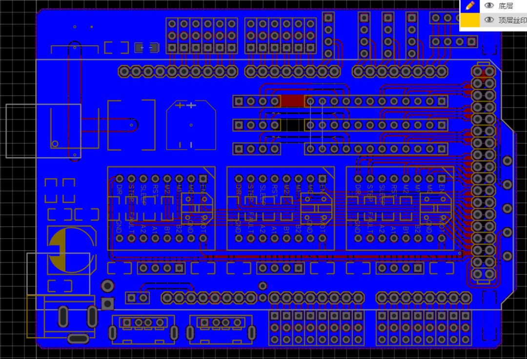
Next is our driver board; the open-source community uses the Arduino Mega board for 3D printers, with various flying wires. Although it has a casing, I personally think it is still a bit messy, so I redesigned the entire driver board~
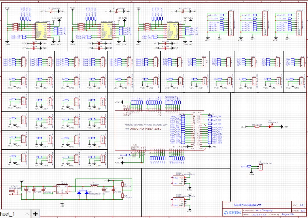
Still using the Arduino Mega2560 development board, I made an expansion board that clips on top. The motor drivers used are 3 DRV8825 and 3 TB6600. For the small motors driven by the DRV8805, I control the micro-stepping pins via the IO ports of the Arduino Mega to achieve software-controlled micro-stepping (I would like to do the same with the TB6600, but I can’t just pull out a few wires from it~)
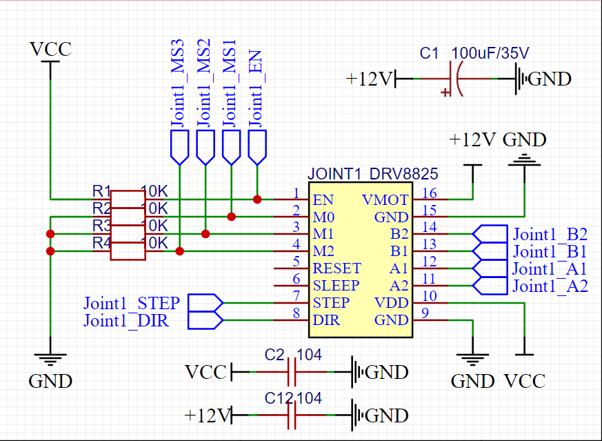
For the DRV8825 driver, I pull the EN pin up with a 10K resistor, keeping it at a high level by default. Meanwhile, I pull down the micro-stepping pins (M0, M1, M2) with a 10K resistor, keeping them at a low level by default. Between 12V and GND, I use a 35V 100uF capacitor and a 0.1uF capacitor in parallel for filtering, which enhances the stability of the motor drive voltage. I also use a 0.1uF capacitor between 5V and GND for filtering to ensure the module signal voltage is stable. All other pins are fully extended.
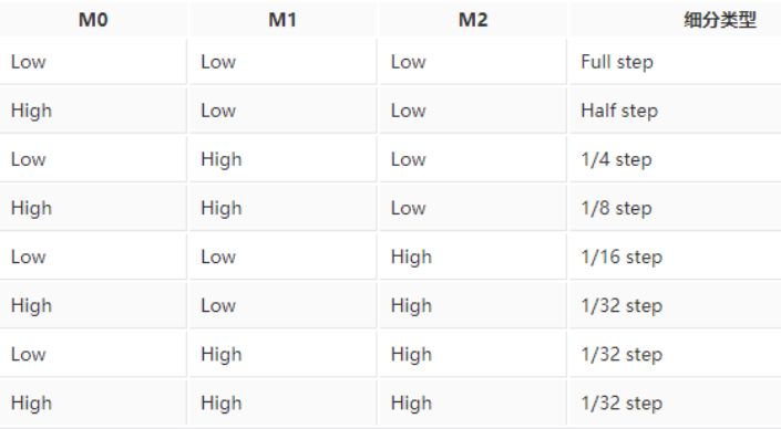
Here is a DRV8825 micro-stepping table for everyone.
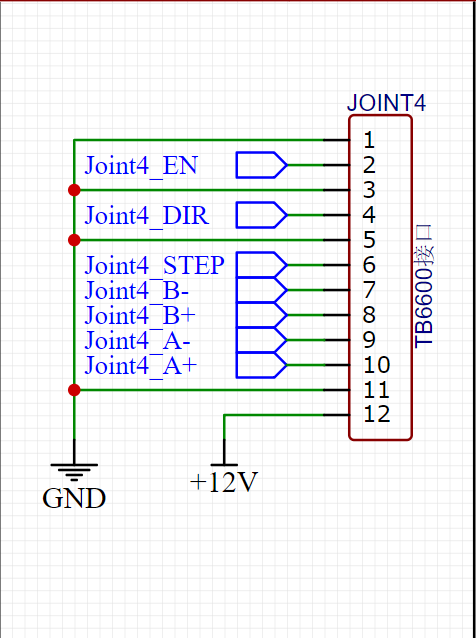
The TB6600 driver is relatively simple, just a straightforward connection is enough. Here, you can also see the position of the flying wires (definitely fewer than theirs).
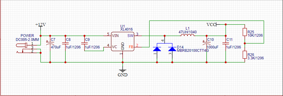
This is our power supply circuit; the working voltage of the robotic arm is 12V. I used an XL4016 IC to convert 12V to 5V 8A. Don’t ask me why I left 5V 8A; considering that the Jetson Nano runs at about 5V 5A, if I also want to charge my phone, I think 5V 8A is quite necessary!
I used a 5.5-2.1 DC connector as the 12V power supply interface, connecting to the output of the switching power supply. At the 12V position, I used a 470uF and a 1uF capacitor in parallel for filtering; VC is the internal voltage adjustment; here we just need to connect a 1uF to 12V; FB is the feedback pin for voltage division, detecting the current output voltage and adjusting it; SW is the power output pin.
After the SW power output, we need to use a fast recovery diode 20100, a 47uH inductor, and a 1000uF capacitor for high-frequency filtering, with a 1uF capacitor as the output filter.
A 10K resistor and a 3.3K resistor are used for voltage division detection; the detection voltage of FB is 1.25V. The 10K resistor is connected to 5V, and the 3.3K resistor is connected to GND, so the voltage difference between the two resistors and GND is approximately 1.25V (1:4 ratio). When the output voltage is insufficient or too high, the XL4016 will automatically adjust.
During use, many IO ports are not utilized, so we will reserve them according to a 3P wiring mode (S, V, G, signal line, power positive, power negative) for easy external connection to other sensors, such as suction cups, servos, etc.
At the same time, serial ports and IIC are also reserved in a 4P wiring mode for external devices.
The driver board also has two USB power supply interfaces reserved, which can charge your phones, power banks, etc.
All IO-related pin functions are as follows.
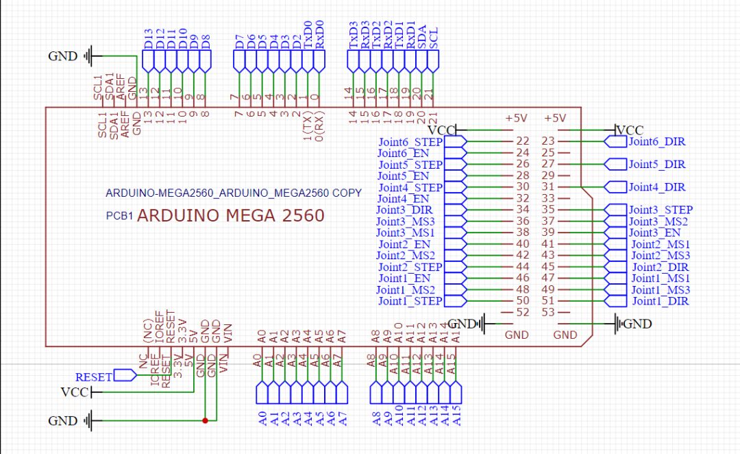
It’s quite nice; the analog ports, PWM, and functional pins are well reserved, although it’s a bit regrettable that SPI couldn’t be reserved. The pin functions are relatively neat, but the difficulty of PCB layout is quite a bitter history~
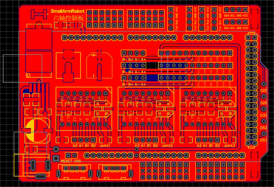
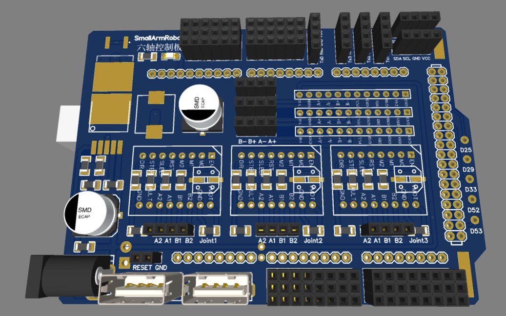
Try to ensure a neat layout, leaving five unused IO ports. You can control something like a suction pump at the end of the robotic arm; the two copper pads are for 5V and GND, which need to be soldered directly for 5V power supply. The PCB has a reset pin reserved; you can connect a button to reset the Arduino Mega when the robotic arm misbehaves (actually due to your code). The two USB ports can power the Jetson Nano or Raspberry Pi, which is quite nice, and charging a phone is also not a problem.
For the power supply part, I used a 12V 8A UPS module and made a 12V 3S battery. The power of the six stepper motors is quite large, but it should not exceed 100W, so 12V 8A should be sufficient.
Once you have connected the robotic arm and the driver board, you can start testing the program. First, write code in Arduino to test whether each motor runs without issues. If everything is fine, we can start developing our ROS robotic arm.
In the ROS development of the robotic arm, we have three function packages: smallarmrobot_description model function package, smallarmrobot_moveit_config function package, and smallarmrobot_driver function package. The smallarmrobot_description package is modified from the leaf_description by the great XueMing, and you can search for it yourself at GuYue Academy. The smallarmrobot_moveit_config package is configured using the moveit_setup_assistant; those who are unfamiliar can refer to the “MoveIt Visualization Configuration and Simulation Guide” tutorial available at GuYue Academy for learning; I won’t go into too much detail here.
(*https://class.guyuehome.com/detail/p_5e71966b3fdfd_g4DpRGg9/6)
In the ROS robotic arm development, the values of the robotic arm’s joint angles are in the position data of the joint_states topic. By subscribing to the position data of the joint_state topic, we can obtain the current radians of each joint of the robotic arm, convert them to angle values, and drive the stepper motors to execute to the corresponding positions. The specific code is as follows.
#!/usr/bin/env python#coding:utf-8 #Import rospy libraryimport rospy #The msg of joint_state belongs to sensorfrom sensor_msgs.msg import JointState #Call StandardFirmata protocolfrom pyfirmata import ArduinoMega,util #Import time functionimport time #Import IO configuration function, customfrom IO_config import * #Stepper motor drive pin declarationJoint_STEP = [Joint1_STEP,Joint2_STEP,Joint3_STEP,Joint4_STEP,Joint5_STEP,Joint6_STEP] #Pulse pin declarationJoint_DIR = [Joint1_DIR,Joint2_DIR,Joint3_DIR,Joint4_DIR,Joint5_DIR,Joint6_DIR] #Direction pin declarationJoint_EN = [Joint1_EN,Joint2_EN,Joint3_EN,Joint4_EN,Joint5_EN,Joint6_EN] #Enable drive pin declaration #Reduction ratio coefficient declaration, recalculation needed herejoint_pro = [joint1_pro,joint2_pro,joint3_pro,joint4_pro,joint5_pro,joint6_pro] #Flag variable declarationjoint_pul_flag = [joint1_pul_flag,joint2_pul_flag,joint3_pul_flag,joint4_pul_flag,joint5_pul_flag,joint6_pul_flag] #Pulse flagjoint_dir_flag = [joint1_dir_flag,joint2_dir_flag,joint3_dir_flag,joint4_dir_flag,joint5_dir_flag,joint6_dir_flag] #Direction flagjoint_value = [joint1_value,joint2_value,joint3_value,joint4_value,joint5_value,joint6_value] #Current angle value #Pulse limitjoint_min_pul = [joint1_min_pul,joint2_min_pul,joint3_min_pul,joint4_min_pul,joint5_min_pul,joint6_min_pul] #Minimum pulse valuejoint_max_pul = [joint1_max_pul,joint2_max_pul,joint3_max_pul,joint4_max_pul,joint5_max_pul,joint6_max_pul] #Maximum pulse value #Instantiate an ArduinoMega object through StandardFirmata protocol, passing in the port number and baud rate, default 8N1 modeboard = ArduinoMega("/dev/ttyUSB0",baudrate=115200) #Enable drive at low levelboard.digital[Joint1_EN].write(0)board.digital[Joint2_EN].write(0)board.digital[Joint3_EN].write(0)board.digital[Joint4_EN].write(0)board.digital[Joint5_EN].write(0)board.digital[Joint6_EN].write(0) '''Function Name: value_driver Function Function: Control the corresponding joint to rotate to the specified angle value Input parameters: joint is the joint number, angle is the target angle value'''def value_driver(joint,angle): #If the current pulse iteration exceeds the operating range, the stepper motor does not execute, output prompt information. This is to avoid over-rotation causing the robotic arm to jam if joint_pul_flag[joint] < joint_min_pul[joint] - 30 or joint_pul_flag[joint] > joint_max_pul[joint] + 30: print("ERROR.Beyond the limit...") else: diff_value = 0 #Angle difference variable declaration step = 0 #Required deployment variable declaration #If the target angle angle is less than the current angle value if angle < joint_value[joint]: joint_dir_flag[joint] = 0 #Set the corresponding joint direction flag to 0 board.digital[Joint_DIR[joint]].write(0) #Direction pin is low diff_value = joint_value[joint] - angle #Calculate angle difference print("Angle value decreases.") #Output prompt information else: joint_dir_flag[joint] = 1 #Set the corresponding joint direction flag to 1 board.digital[Joint_DIR[joint]].write(1) #Direction pin is high diff_value = angle - joint_value[joint] #Calculate angle difference print("Angle value increases.") #Output prompt information print("Angle difference is: " + str(diff_value)) #Output the calculated angle difference step = int(diff_value/joint_pro[joint]) #Steps = angle value / reduction ratio print("Required pulse count: " + str(step) +.") #Output prompt information, required pulse count #Send the specified number of pulses to execute the drive while step > 0: board.digital[Joint_STEP[joint]].write(1) time.sleep(0.01) board.digital[Joint_STEP[joint]].write(0) time.sleep(0.01) step = step - 1 print("Pulse execution complete.") #Output prompt information step = int(diff_value/joint_pro[joint]) if joint_dir_flag[joint] == 0: joint_pul_flag[joint] = joint_pul_flag[joint] - step #Update current pulse flag else: joint_pul_flag[joint] = joint_pul_flag[joint] + step print("Pulse count iteration complete. Current pulse count is " + str(joint_pul_flag[joint]) + ".") #Output prompt information, pulse accumulation joint_value[joint] = angle #Angle value iteration print("Angle iteration complete. Current angle is " + str(joint_value[joint]) + ".") #Output prompt information, current angle value '''Function Name: callback Function Function: Execute as a callback function''' def callback(data): joint6_angle = data.position[0]*360/6.28+90 #Convert the corresponding joint radians to angle value #Check if the current angle value is out of bounds if joint6_angle<0: #If the current angle value is less than 0, set the angle value to 0 to avoid negative numbers joint6_angle = 0 elif joint6_angle>180: #If the current angle value is greater than 180, set the angle value to 180 to avoid exceeding the angle joint6_angle = 180 rospy.loginfo(rospy.get_caller_id() + ']--->Joint6 Angle :%d', joint6_angle) #ros output prompt information #value_driver(5,joint6_angle) #Execute angle value #Similarly joint5_angle = data.position[1]*360/6.28+90 if joint5_angle<0: joint5_angle = 0 elif joint5_angle>180: joint5_angle = 180 rospy.loginfo(rospy.get_caller_id() + ']--->Joint5 Angle :%d', joint5_angle) value_driver(4,joint5_angle) joint4_angle = data.position[2]*360/6.28+90 if joint4_angle<0: joint4_angle = 0 elif joint4_angle>180: joint4_angle = 180 rospy.loginfo(rospy.get_caller_id() + ']--->Joint4 Angle :%d', joint4_angle) value_driver(3,joint4_angle) joint3_angle = data.position[3]*360/6.28+90 if joint3_angle<0: joint3_angle = 0 elif joint3_angle>180: joint3_angle = 180 rospy.loginfo(rospy.get_caller_id() + ']--->Joint3 Angle :%d', joint3_angle) value_driver(2,joint3_angle) joint2_angle = data.position[4]*360/6.28+90 if joint2_angle<0: joint2_angle = 0 elif joint2_angle>180: joint2_angle = 180 rospy.loginfo(rospy.get_caller_id() + ']--->Joint2 Angle :%d', joint2_angle) value_driver(1,joint2_angle) joint1_angle = data.position[5]*360/6.28+90 if joint1_angle<0: joint1_angle = 0 elif joint1_angle>180: joint1_angle = 180 rospy.loginfo(rospy.get_caller_id() + ']--->Joint1 Angle :%d', joint1_angle) value_driver(0,joint1_angle) def driver(): rospy.init_node('SmallArmRobot_Driver', anonymous=True) #Initialize the node, named SmallArmRobot_Driver rospy.Subscriber('joint_states', JointState, callback) #Subscribe to the joint_states topic, type is JointState, execute callback function when subscribed rospy.spin() if __name__ == '__main__': driver()board.exit()It is important to understand the functionality of the value_driver function.
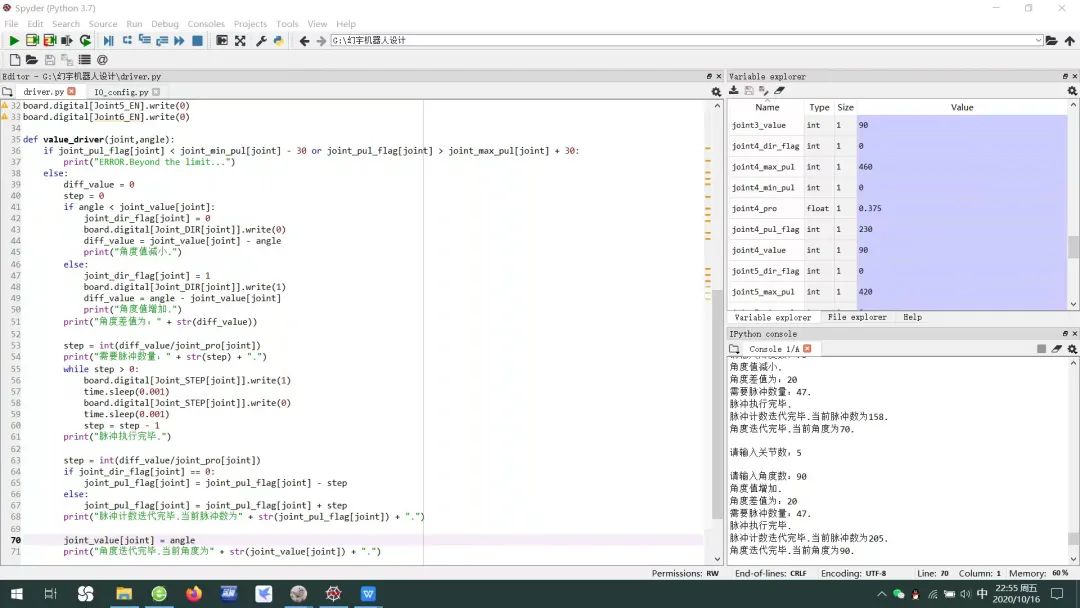
This is the data I captured during validation; the function of value_driver is to treat the stepper motor like a servo, turning to a specified angle when given an angle value. Currently, the algorithm I designed has a large error, and the dynamic switching effect of the micro-stepping pins has not been developed yet, which is also a task I need to complete in the next phase. You can also browse the driving code provided by SmallArmRobot, which has relatively high precision.
# -*- coding: utf-8 -*-"""Created on Fri Oct 16 19:37:56 2020 @author: 嘉""" '''''''''''''''''''''''''Arduino Mega pin IO declaration'''''''''''''''''''''''''Joint1_DIR = 51Joint1_STEP = 50Joint1_MS3 = 49Joint1_MS2 = 48Joint1_MS1 = 47Joint1_EN = 46 Joint2_DIR = 45Joint2_STEP = 44Joint2_MS3 = 43Joint2_MS2 = 42Joint2_MS1 = 41Joint2_EN = 40 Joint3_EN = 39Joint3_MS1 = 38Joint3_MS2 = 37Joint3_MS3 = 36Joint3_STEP = 35Joint3_DIR = 34 Joint4_EN = 32Joint4_DIR = 31Joint4_STEP = 30 Joint5_EN = 28Joint5_DIR = 27Joint5_STEP = 26 Joint6_EN = 24Joint6_DIR = 23Joint6_STEP = 22 '''''''''''''''Reduction ratio coefficients'''''''''''''''joint1_pro = 1.8joint2_pro = 0.8joint3_pro = 0.6joint4_pro = 0.375joint5_pro = 0.42joint6_pro = 0.375 '''''''''''''''Flag variable declaration'''''''''''''''joint1_pul_flag = 0joint1_dir_flag = 0joint1_value = 0 joint2_pul_flag = 105joint2_dir_flag = 0joint2_value = 90 joint3_pul_flag = 150joint3_dir_flag = 0joint3_value = 90 joint4_pul_flag = 230joint4_dir_flag = 0joint4_value = 90 joint5_pul_flag = 210joint5_dir_flag = 0joint5_value = 90 joint6_pul_flag = 240joint6_dir_flag = 0joint6_value = 90 '''''''''''''''Limit flag declaration'''''''''''''''joint1_min_pul = 0joint1_max_pul = 200 joint2_min_pul = 0joint2_max_pul = 210 joint3_min_pul = 0joint3_max_pul = 300 joint4_min_pul = 0joint4_max_pul = 460 joint5_min_pul = 0joint5_max_pul = 420 joint6_min_pul = 0joint6_max_pul = 480This section contains the content of our IO_config file, which mainly defines some parameters. The reduction ratios involved can be calculated; it essentially means how many degrees the robotic arm can turn with a pulse under the current reduction ratio. You might not see the angle with just one pulse. I calculated how many pulses are needed for each joint at 0 degrees, 90 degrees, 180 degrees, etc., and did a division to obtain the reduction ratio. Steps = Angle value / Reduction ratio.
You can run the smallarmrobot_description model function package to control the joints of the SmallArmRobot through a progress bar, or you can experience motion planning through the demo.launch of the smallarmrobot_moveit_config package. Experts can also use the MoveIt programming interface to control the robotic arm~
Everyone is welcome to design their own algorithms for controlling stepper motors, and I encourage you to innovate based on existing foundations. Let’s learn and progress together!
Relevant materials can be downloaded through the following link; if the link expires, please contact the GuYue Academy public account!
Link:

“MoveIt! Play with Dual-Arm Robot” In ROS, developing a robotic arm is not just about making it move; it is more about learning how to use the MoveIt! programming interface. This tutorial will guide everyone in designing a dual-arm robotic arm based on MoveIt!, and we will also design a teaching device to control our robotic arm.

(Scan the QR code to view course details)