
 01Introduction:
The HC32L196_L190 series is widely used in the following scenarios:
IoT Devices: In IoT devices, the high performance and low power characteristics of the HC32L196_L190 series microcontrollers enable efficient operation over extended periods.
Smart Home: In the smart home sector, microcontrollers can be used to control various appliances, such as air conditioning and lighting, achieving intelligent control.
Industrial Control: In the field of industrial control, the high performance and rich peripheral interfaces of the HC32L196_L190 series microcontrollers make them ideal control cores.
Automotive Electronics: In automotive electronics, microcontrollers can be used to control various automotive electronic systems, such as body control and power systems.
Enough talk, let’s get straight to the essentials.
02Code and Configuration Principles
1. Code
#include "ddl.h"
#include "uart.h"
#include "gpio.h"
#include <stdio.h>

void App_UartCfg(uint32_t baud);
void App_PortInit(void);
void App_LedInit(void);

int32_t main(void)
{
    Sysctrl_SetHCLKDiv(SysctrlHclkDiv1);
    Sysctrl_SetPCLKDiv(SysctrlPclkDiv1);
    App_PortInit();
    App_UartCfg(115200);
    App_LedInit();
    while(1)
    {
        printf("--->uart test\r\n");
        Gpio_SetIO(STK_LED_PORT, STK_LED_PIN); // Turn on LED
        delay1ms(1000);
        Gpio_ClrIO(STK_LED_PORT, STK_LED_PIN); // Turn off LED
        delay1ms(1000);
    }
    return 0;
}
// UART pin configuration
void App_PortInit(void)
{
    stc_gpio_cfg_t stcGpioCfg;
    DDL_ZERO_STRUCT(stcGpioCfg);
    Sysctrl_SetPeripheralGate(SysctrlPeripheralGpio, TRUE); // Enable GPIO module clock
    // TX configuration
    stcGpioCfg.enDir = GpioDirOut;
    Gpio_Init(GpioPortB, GpioPin8, &stcGpioCfg);
    Gpio_SetAfMode(GpioPortB, GpioPin8, GpioAf7);          // Configure PB08 port as UART0_TX
    // RX configuration
    stcGpioCfg.enDir = GpioDirIn;
    Gpio_Init(GpioPortB, GpioPin9, &stcGpioCfg);
    Gpio_SetAfMode(GpioPortB, GpioPin9, GpioAf7);          // Configure PB09 port as UART0_RX
}
// UART configuration
void App_UartCfg(uint32_t baud)
{
    stc_uart_cfg_t    stcCfg;
    uint32_t u32Pclk;
    DDL_ZERO_STRUCT(stcCfg);
    // Enable peripheral clock
    Sysctrl_SetPeripheralGate(SysctrlPeripheralUart0, TRUE); // Enable UART0 module clock
    u32Pclk = Sysctrl_GetPClkFreq();
    if(u32Pclk == 0)
    {
        while(1); // Clock error handling
    }
    // UART Init
    stcCfg.enRunMode        = UartMskMode1;          // Mode 1
    stcCfg.enStopBit        = UartMsk1bit;           // 1 bit stop bit
    stcCfg.stcBaud.u32Baud  = baud;                  // Baud rate
    stcCfg.stcBaud.enClkDiv = UartMsk8Or16Div;       // Channel sampling division configuration
    stcCfg.stcBaud.u32Pclk  = u32Pclk;               // Get peripheral clock (PCLK) frequency value
    Uart_Init(M0P_UART0, &stcCfg);                   // UART initialization
}
void App_LedInit(void)
{
    stc_gpio_cfg_t stcGpioCfg;
    // Open GPIO peripheral clock gating
    Sysctrl_SetPeripheralGate(SysctrlPeripheralGpio, TRUE);
    stcGpioCfg.enDir = GpioDirOut;
    // Port pull-up/pull-down configuration -> pull-down
    stcGpioCfg.enPu = GpioPuDisable;
    // LED off
    Gpio_ClrIO(STK_LED_PORT, STK_LED_PIN);
    // GPIO IO LED port initialization
    Gpio_Init(STK_LED_PORT, STK_LED_PIN, &stcGpioCfg);
}
int fputc(int ch, FILE* f)
{
    Uart_SendDataPoll(M0P_UART0, ch);
    return (ch);
}
2. Configuration Principles
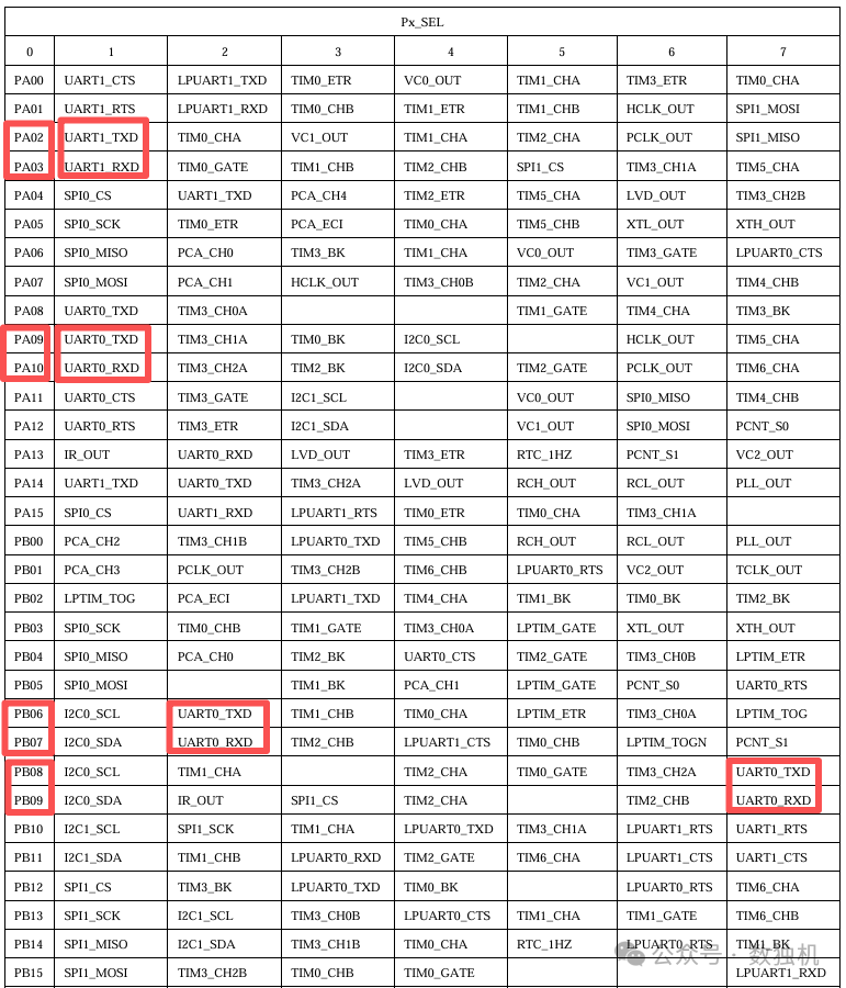 03Conclusion: Be sure to check the corresponding relationship of the multiplexing. Choose the multiplexing group that matches the schematic for the TX and RX pins.