Background Knowledge of Communication Interfaces
Ways of Communication Between Devices
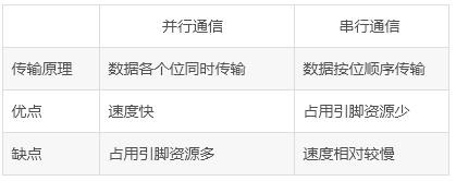
Generally, the communication methods between devices can be divided into parallel communication and serial communication. The differences between parallel and serial communication are shown in the table below.
Classification of Serial Communication
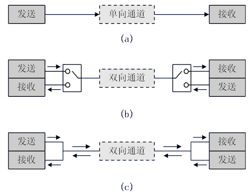
1. According to the direction of data transmission, it can be divided into:
-
Simplex: Data transmission only supports data transmission in one direction; -
Half-duplex: Allows data to be transmitted in both directions. However, at any given time, data is only allowed to be transmitted in one direction, which is essentially a switched direction simplex communication; it does not require independent receiving and transmitting ends, and both can be combined to use one port. -
Full-duplex: Allows data to be transmitted simultaneously in both directions. Therefore, full-duplex communication is a combination of two simplex communication methods, requiring independent receiving and transmitting ends.
2. According to the communication method, it can be divided into:
-
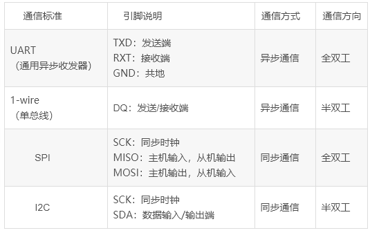
Synchronous communication: Transmission with clock synchronization signals. For example: SPI, IIC communication interfaces. -
Asynchronous communication: Without clock synchronization signals. For example: UART (Universal Asynchronous Receiver-Transmitter), single bus.
In synchronous communication, a signal line is used to transmit signals above the sending and receiving devices, and both parties coordinate and synchronize data under the drive of the clock signal. For example, it is usually agreed that the data line is sampled on the rising edge or falling edge of the clock signal during communication.
In asynchronous communication, clock signals are not used for data synchronization; instead, they directly intersperse some synchronization signal bits in the data signal or package the subject data to transmit data in the format of data frames. Both parties also need to agree on the data transmission rate (i.e., baud rate) to achieve better synchronization. Common baud rates include 4800bps, 9600bps, 115200bps, etc.
In synchronous communication, the content transmitted by the data signal is mostly valid data, while asynchronous communication includes various identifiers of data frames. Therefore, synchronous communication is more efficient, but the clock error is allowed to be small for both parties in synchronous communication; a slight clock error may lead to data confusion, while asynchronous communication allows for larger clock errors.
Common Serial Communication Interfaces
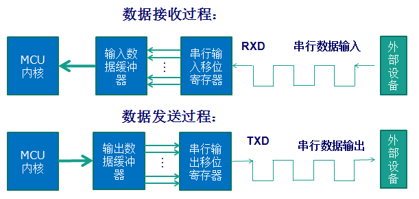
Basic Serial Communication of STM32
STM32’s serial communication interface includes two types: UART (Universal Asynchronous Receiver-Transmitter) and USART (Universal Synchronous Asynchronous Receiver-Transmitter). For the high-capacity STM32F10x series chips, there are three USARTs and two UARTs.
-
RXD: Data input pin, receives data; -
TXD: Data output pin, sends data.
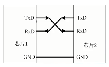
For the connection between two chips, both chips share a common ground (GND), and TXD and RXD are crossed connected. The meaning of crossed connection here is that chip 1’s RXD connects to chip 2’s TXD, and chip 2’s RXD connects to chip 1’s TXD. In this way, TTL level communication can be established between the two chips. For examples of STM32 serial communication with 51 microcontrollers, please move to:STM32 and 51 Microcontroller Serial Communication Examples.
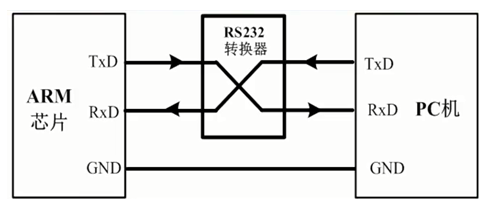
If the chip is connected to a PC (or host computer), in addition to sharing a common ground, direct crossed connection cannot be made. Although both the PC and the chip have TXD and RXD pins, the PC (or host computer) usually uses the RS232 interface (usually DB9 package), so direct crossed connection is not possible. The RS232 interface has 9 pins (or terminals), and usually, TxD and RxD are obtained through level conversion. Therefore, to allow the chip to communicate directly with the PC’s RS232 interface, the chip’s input and output ports must also be converted to RS232 type before crossed connection.
-
Microcontroller voltage standard (TTL level): +5V represents 1, 0V represents 0; -
RS232 voltage standard: +15/+13 V represents 0, -15/-13 represents 1.
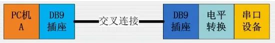
The communication structure diagram between devices in the RS-232 communication protocol standard serial port is as follows:
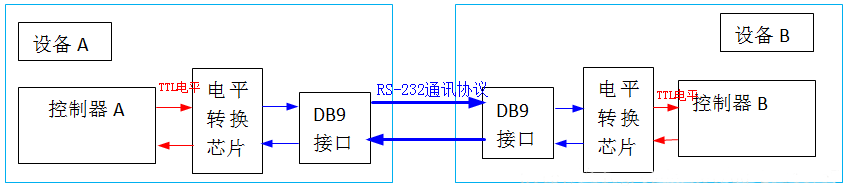
Therefore, the connection between the microcontroller’s serial port and the PC’s serial port should follow the connection method below: between the microcontroller’s serial port and the RS232 port provided by the host computer, a level conversion circuit (such as the Max232 chip in the figure below) is used to realize the conversion between TTL level and RS232 level. For examples of communication between STM32 and PC, please move to:STM32 Example – Control Serial Data Transmission with a Key, with code at the end of the article.
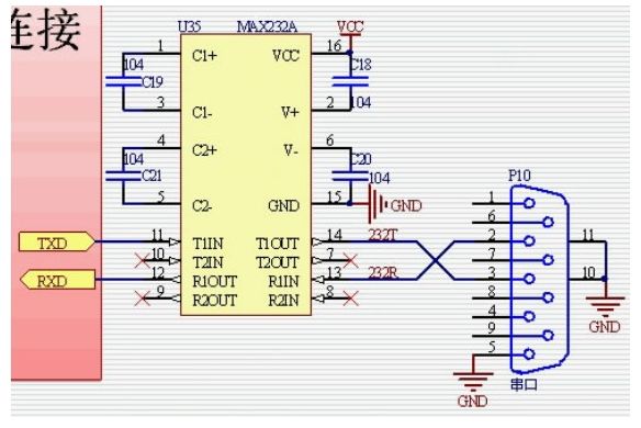
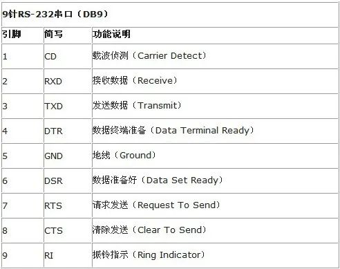
Only two pins participate in the communication process.
-
Pin 2: Computer input RXD
-
Pin 3: Computer output TXD. Through pins 2 and 3, full-duplex (simultaneous send and receive) serial asynchronous communication can be achieved.
-
Pin 5: Ground.
The microcontroller’s P3 port has two multiplexed interfaces RXD and TXD. This is the transceiver port for the microcontroller’s serial communication, and the connection should be misaligned to correspond to the computer’s TDX and RDX. Note: The voltage standards of the microcontroller and RS232 are not the same.
The microcontroller’s voltage standard (TTL level): +5V represents 1, 0V represents 0.
The RS232 voltage standard: +15/+13 V represents 1, -15/-13 represents 0.
Therefore, the connection between the microcontroller and the computer’s serial port should follow the connection method below:
Between the microcontroller and the RS232 port provided by the host computer, a level conversion circuit (the Max232 chip in the figure above) is used to realize the conversion between TTL level and RS232 level, PC serial port and microcontroller serial port connection diagram:
Note these two DB9: DB91 is on the computer and DB92 is soldered on the microcontroller experiment board.
The meaning of crossed connection here is that DB91’s RXD is connected to DB92’s TXD.
DB92’s RXD is connected to DB91’s TXD, thus crossed connection. If the computer does not have an RS232 port but only a USB port, a serial port adapter can be used to convert it to a serial port, as shown in the figure below.
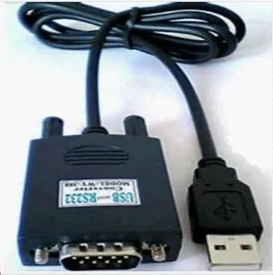
At this time, a serial port driver needs to be installed on the computer’s host.
Note that this driver is for the PL2303 chip (inside the large head in the above figure), which converts RS232 information into USB information.
The figure below shows the internal structure of the above figure:
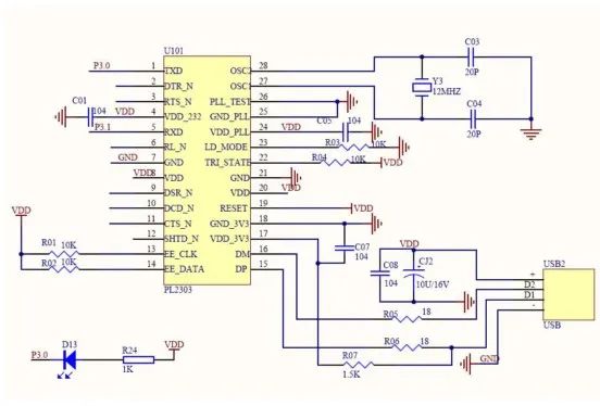
Using serial communication is simpler than USB because serial communication does not have protocols and is easy to use.
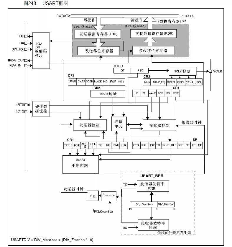
-
Full-duplex asynchronous communication;
-
Fractional baud rate generator system, providing precise baud rates. Shared programmable baud rate for sending and receiving, up to 4.5Mbits/s;
-
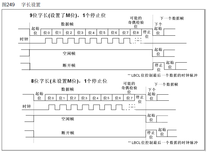
Programmable data word length (8 or 9 bits);
-
Configurable stop bits (supports 1 or 2 stop bits);
-
Configurable DMA multi-buffer communication;
-
Separate transmitter and receiver enable bits; -
Detection flags:
① Receive buffer
② Transmit buffer empty
③ Transmission end flag;
-
Multiple interrupt sources with flags to trigger interrupts;
-
Others: Parity control, four error detection flags.
UART Parameters in STM32
More Exciting:
Yan Shi│Reflections and Suggestions on the “Dilemmas” of Young Teachers in Universities
Academician Zheng Weimin: Why Computer Majors Have Become a Hot Choice for Examinees
【Directory】”Computer Education” July 2022 Issue
【Directory】”Computer Education” June 2022 Issue
【Directory】”Computer Education” May 2022 Issue
【Directory】”Computer Education” April 2022 Issue
【Directory】”Computer Education” March 2022 Issue
【Directory】”Computer Education” February 2022 Issue
【Directory】”Computer Education” January 2022 Issue
【Editorial Committee Message】Professor Li Xiaoming from Peking University: Thoughts from the “Year of Improvement in Classroom Teaching”…
Professor Chen Daoxu from Nanjing University: Which is more important, teaching students to ask questions or teaching students to answer questions?
【Yan Shi Series】: Trends in Computer Discipline Development and Their Impact on Computer Education
Professor Li Xiaoming from Peking University: From Fun Mathematics to Fun Algorithms to Fun Programming – A Path for Non-professional Learners to Experience Computational Thinking?
Reflections on Several Issues in First-Class Computer Discipline Construction
Professor Zhan Dechen from Harbin Institute of Technology Answers 2000 Questions on AI
Professor Zhou Aoying, Vice President of East China Normal University: Accelerating the Advancement of Computer Science Education and Being a Pathfinder in Data Science Education – Interview with Professor Zhou Aoying
New Engineering and Big Data Major Construction
Learning from Others to Improve Oneself – Compilation of Research Articles on Computer Education at Home and Abroad