Wherever there is electricity, printed circuit boards (PCBs) are needed.
1. Definition of AOI
The full name of AOI is Automated Optical Inspection, which translates to 自动光学检测 in Chinese.
It is a high-speed, high-precision device that uses optical principles, high-resolution cameras, and precision motion control systems to automatically detect various defects on printed circuit boards (PCBs) through image processing algorithms.
In simple terms, AOI is like equipping the PCB production line with a tireless “golden eye,” capable of quickly and accurately identifying tiny defects that are difficult for the human eye to detect, operating 24/7.
2. Role of AOI
AOI plays a crucial role as a “quality gatekeeper” in the PCB manufacturing process, with its main functions including:
1. Improving product quality: By detecting and removing defective boards, it prevents defective products from flowing into subsequent processes or being delivered to customers, directly enhancing the yield and reliability of the final product.
2. Process monitoring and early warning: Real-time collection of defect data during production (such as which defects are common, where they occur, and at what times) helps process and equipment engineers quickly locate the root causes of problems (e.g., open circuits, missing components, residual copper shorts, fat/skinny line anomalies, etc.), transitioning from “post-inspection” to “process prevention.”
3. Reducing production costs: The earlier defects are detected, the lower the repair costs. If defects are found after placement or before soldering, repairs may only require replacing a single component; however, if defects are discovered during final testing or product usage, repair costs can increase exponentially (potentially requiring the replacement of the entire board or product).
4. Enhancing production efficiency: Replacing traditional manual visual inspection, detection speed is extremely fast (usually measured in seconds) and is not affected by fatigue, emotions, or other factors that could impact judgment consistency and accuracy, meeting the high rhythm requirements of modern SMT production lines.
5. Data traceability and analysis: All inspection results are recorded and generate reports, facilitating quality traceability and long-term production data analysis, providing data support for continuous improvement.
3. Key Control Parameters
The detection capability of AOI largely depends on the settings of its parameters. Key control parameters can be divided into two main categories:
A. Front-end detection parameters (related to image acquisition and algorithms)
1. Brightness/Lighting parameters: · Light source configuration: Typically uses multi-color (red, green, blue, white) ring lights or multi-angle light sources. Different colors of light striking different materials (such as component bodies, pads, solder paste) will create different contrasts. The best combination of light sources and illumination angles must be selected based on the detection object (e.g., solder joints, missing components, polarity). · Light intensity: Insufficient intensity can lead to low signal-to-noise ratios and unclear features; excessive intensity can cause reflections that obscure real defects.
2. Detection algorithms and tolerances: · Algorithm selection: For different detection items (such as missing components, offsets, polarity, tombstoning, bridging, cold solder joints, etc.), the most suitable algorithm (such as grayscale comparison, feature extraction, color analysis, 3D height measurement, etc.) must be selected. · Detection frame size and position: The feature area to be detected must be accurately defined. · Grayscale/color tolerances: Set the grayscale or color range of the qualified product image features. If the tolerance is set too tight, false calls will increase; if set too loose, the risk of escapes will increase. This is a core parameter that requires repeated tuning and optimization.
3. Resolution and magnification: · Select appropriate camera resolution and optical magnification based on the precision of the components being detected (e.g., 0201, 01005 micro components or fine-pitch BGA, QFP) to ensure sufficient detail is captured.
B. Back-end judgment parameters (related to data flow and judgment)
1. False Call Rate: The proportion of good boards misjudged as defects by AOI. Programs must be continuously optimized to reduce the false call rate; otherwise, it will waste a lot of re-inspection manpower.
2. Escape Rate: The proportion of real defects that are not detected by AOI and flow out. This is the most critical indicator of AOI effectiveness and needs to be verified through regular testing with known defect boards (Golden Boards).
3. First Pass Yield: The proportion of boards that pass inspection on the first attempt, reflecting the overall stability of the production line and the rationality of the AOI program settings.
4. Control Points
To ensure the AOI system operates stably and effectively, attention must be paid to the following control points:
1. Program creation and optimization: · Golden Board: Select a perfectly crafted board as the standard board for initial program creation and subsequent regular verification. · Application of deep learning/AI: For complex solder joint inspections (especially for conformal coatings or black solder masks), traditional algorithms face significant challenges. Using AI-based detection technology can greatly reduce the false call rate and better detect complex defects. · Panel optimization: For panels, only one or two small boards can be finely programmed, then copied to other small boards, with minor adjustments to the mark point offsets, greatly improving programming efficiency.
2. Daily maintenance and calibration of equipment: · Regular cleaning: The camera lens, light source glass cover, and stage must be regularly cleaned to prevent dust and stains from causing misjudgments. · Light source calibration: LED light sources will degrade over time, requiring regular brightness calibration to ensure image consistency. · System accuracy calibration: Regularly calibrate the mechanical and optical systems of the equipment using standard calibration boards.
3. Personnel training and management: · Operator training: Operators must master basic equipment operation, daily maintenance, and simple false call re-inspection skills. · Programmer training: Programmers are the core of the AOI system and must have a deep understanding of processes, defect patterns, and algorithm principles, with excellent program optimization and data analysis skills. · Re-inspection discipline: For boards flagged by AOI, re-inspection personnel must strictly follow standards for confirmation, without arbitrarily passing or discarding, and provide timely feedback to programmers for program optimization.
4. Application Scenarios in PCB Manufacturing
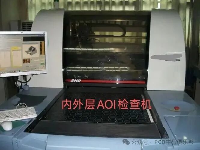
a) Inner/Outer Layer Pattern AOI: By scanning the physical appearance of the inner/outer layer patterns and comparing them with the standard board pattern data set in the system, it can identify and recognize defects such as open circuits, missing sections, residual copper, and short circuits. Coupled with VRS repair machines, these minor defects can be repaired according to standards, while severe defects that cannot be repaired are scrapped and marked as such.
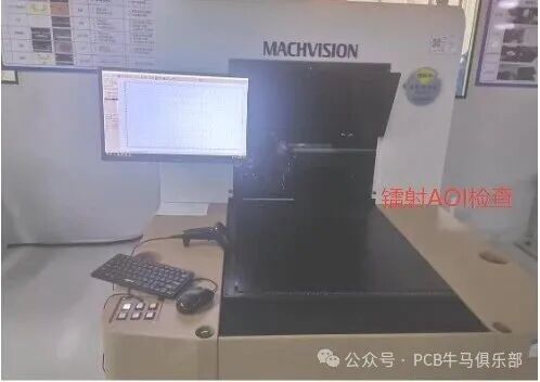
b) Laser AOI Inspection Machine: Mainly targets boards after laser processing, scanning the surface and blind holes to identify defects such as multiple/few holes, oversized/undersized holes, misaligned holes, and residual glue inside holes.
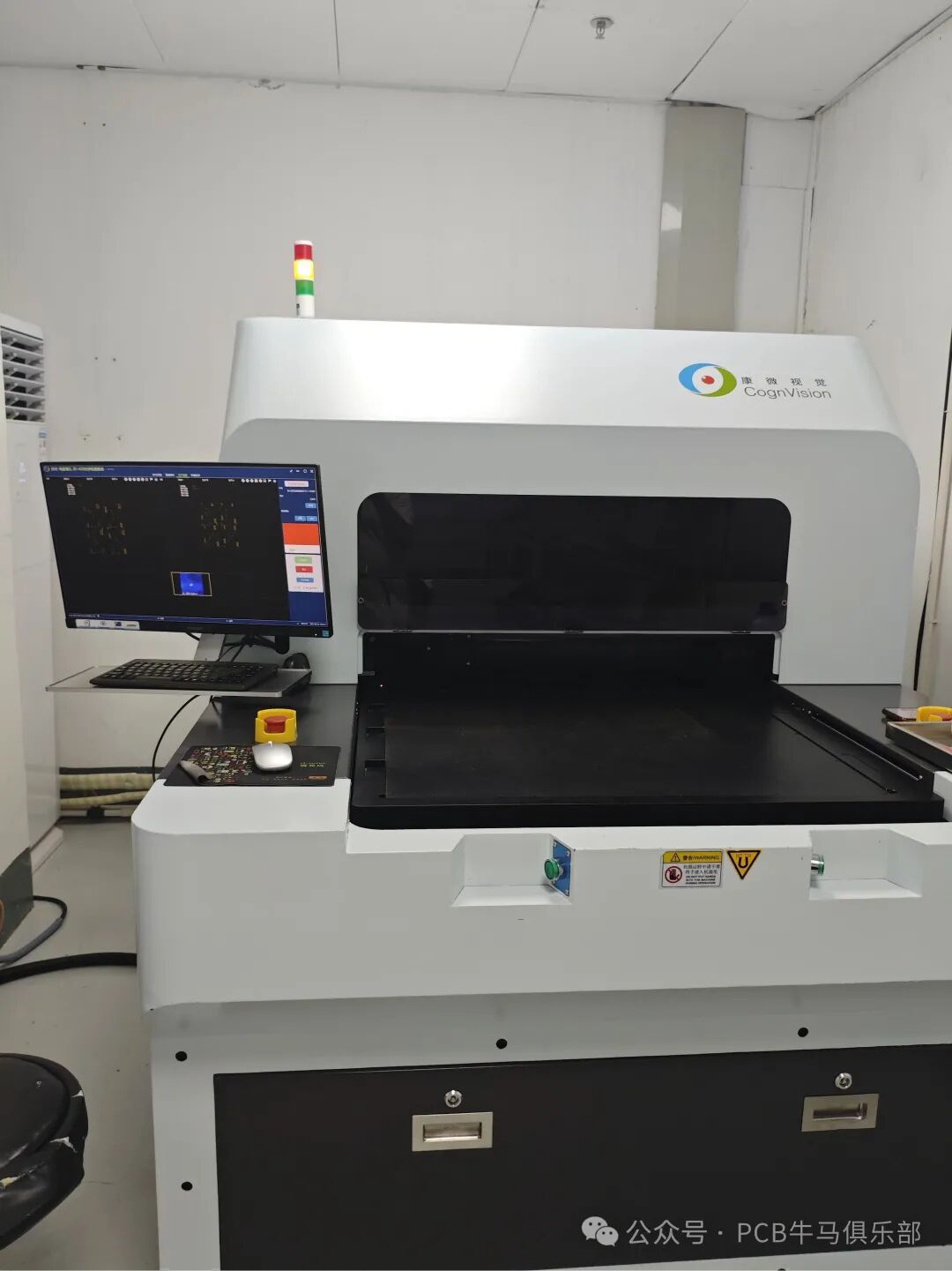
c) Blind Hole Depth AOI Inspection Machine: Scans blind hole boards after electroplating to accurately measure the depth of blind holes or the height of protrusions, serving as a means for monitoring the quality of blind hole electroplating.
 d) Fully Automatic Line Width Inspection Machine: Through optical scanning, all line patterns, BGA, SMT, optical points, and impedance strips can be accurately measured, serving as an important means for first-piece inspection of inner and outer layer line widths.
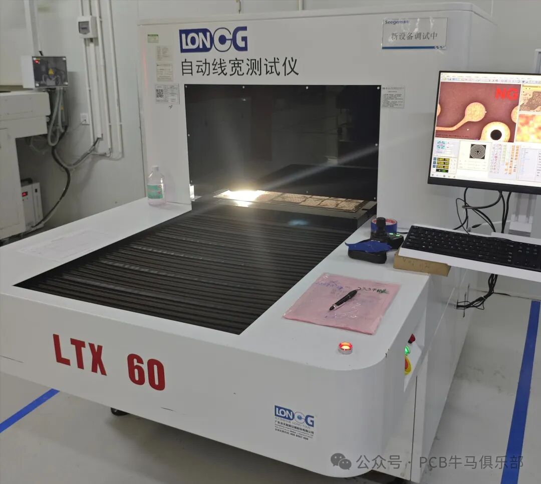 e) Finished Product AOI Appearance Inspection MachineConducts comprehensive appearance inspections and scans of finished PCB boards, accurately identifying defects such as scratches, broken lines, oxidation, green oil on pads, missing printed characters, missing drill holes, missing routing, and missing V-CUTs.
5. Integration with MES Systems: · Integrating AOI with Manufacturing Execution Systems (MES) allows for real-time uploading of inspection results, data analysis, and production dashboard management, achieving true digital and intelligent quality control. Structurally, AOI inspection equipment can be divided into three main types: simple manual offline AOI devices, online AOI devices, and offline AOI devices. Among them, online AOI devices are particularly suitable for placement on production lines to work synchronously with other equipment, maintaining a detection rhythm consistent with the production line, and can be flexibly placed at any position on the production line based on different detection needs. Offline AOI devices, however, do not have the functionality for use on production lines but can perform independent inspection work on PCBs/PCBAs from other suitable locations.
Currently, AOI optical inspection instruments mainly use two inspection comparison technologies: statistical modeling and feature vector analysis. AOI devices are categorized into simple, online, and offline devices, which can be further subdivided by resolution and configuration to meet different inspection needs, ensuring product quality in circuit board production.
Online AOI and offline AOI share the commonality of relying on a fusion of deep learning algorithms and traditional algorithms. The core differences mainly lie in their application methods and applicable scenarios. Online AOI focuses more on real-time detection, quickly capturing and analyzing defects during the production process, providing strong support for quality control on the production line. Offline AOI, on the other hand, is more suitable for comprehensive and detailed inspections of produced products to ensure that each product meets quality standards.
Other types of AOI devices, such as those categorized by resolution, can include 1.0402 component AOI devices and 2.0201 component AOI devices, which can be used in different production stages based on inspection needs, ensuring high quality for various PCB and PCBA products. AOI devices, through their specialized detection functions, ensure the accuracy and rigor of bare board inspections in the PCB industry, providing strong quality assurance for large-scale production of electronic products.
Currently, brands of AOI equipment for line patterns include Aobo, Kangdai, Eagle Eye, Mude, Pangu, and others.
Conclusion
AOI is an indispensable quality inspection tool in modern PCB and SMT manufacturing. It is not only a “detection” tool but also a powerful “process control” and “data analysis” tool. The key to effectively utilizing AOI lies in: precise program settings, continuous parameter optimization, strict equipment maintenance, and in-depth data analysis, thus forming a complete quality feedback loop from detection to feedback to process improvement.
Special Note: The above discussion is for reference only and serves as a starting point for further exploration! Each factory’s chemicals/processes/equipment/product structures, etc., have various differences, and one must not rigidly apply these insights; effective improvement measures must always be based on experimental data! As a professional quality of engineering technicians, one must “speak with data.”Source: Compiled from internet materials for the purpose of communication and learning.
This public account will continue to update information related to PCB manufacturing and cutting-edge technologies, please “follow” to avoid missing the content you need.
If this has been helpful to you, please follow + bookmark ➕ share ➕ like, thank you!
Not only does it look good and handsome, but it can also move its golden fingers to make money, so please follow + bookmark + share + like!!!