Do you remember the first and second episodes of Fei’s knowledge nuggets?Do you recall the explanation about Arduino?(If you haven’t seen it, click the image below to check it out👇)(Remember to come back after watching)Are you still a bit confused?To make it more vivid and less boring, let’s understand Arduino through a complete beginner’s example.
Arduino Programming Practical Teaching
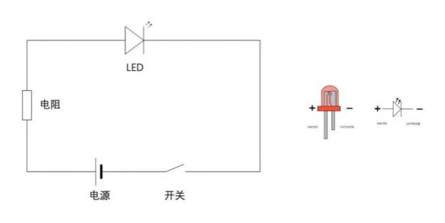
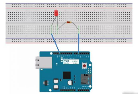
Before we start, you should have the following basic knowledge:1) Middle school physics and electrical knowledge;2) Basic programming knowledge: variables, functions, etc.Additionally, it’s best to have an Arduino development kit. Here we are using the Arduino UNO R3, which is suitable for beginners, so you can buy one by searching for “Arduino UNO R3” on Taobao.Arduino IDEOpen the official Arduino website, navigate to “SOFTWARE – DOWNLOADS”, and select the version corresponding to your operating system to download it. After downloading, install it.Take out the Arduino development board and a USB printer cable, connect the USB to the computer and the other end to the Arduino development board.Arduino development board and data cableThe first time you open the Arduino IDE, you need to set the board and port.When Arduino IDE starts, it will automatically open a file named “sketch_date”. Press “Cmd + S” to save it, and you can rename it and specify the save directory.Arduino Example – Blinking LEDHow do we make an LED light up? Let’s look at a physics circuit diagram we learned in middle school.LED Circuit DiagramThe power supply in the circuit diagram is responsible for providing power. When the switch is turned on, the current flows from the positive terminal of the LED to the negative terminal, and the LED lights up. When the current flows from the LED’s positive terminal to the negative terminal, the resistance is approximately 0, essentially acting like a wire. Therefore, to prevent the positive and negative terminals of the power supply from connecting directly, a resistor is needed. When the current flows from the LED’s negative terminal to the positive terminal, the resistance is almost infinite, which is equivalent to an open circuit. Thus, when connecting the LED, it is crucial to distinguish between the positive and negative terminals. In reality, the longer lead of the LED is the positive terminal, and the shorter lead is the negative terminal.Arduino Implementation Circuit DiagramSo how do we implement the connections in the circuit diagram using Arduino? Let’s look at the simulation diagram below.Arduino Circuit DiagramIn the simulation diagram, the Arduino development board acts as the power supply, with one end of the wire connected to the resistor and the other end connected to the Arduino’s pin 5, while the wire connected to the LED’s other end connects to the Arduino’s GND port. What is the principle behind this connection?GND stands for Ground, which means grounding and provides a reference potential (0V) for the circuit. When a voltage greater than 0V is applied to Arduino’s pin 5, current flows through the circuit, illuminating the LED. If the voltage at pin 5 is 0V, there will be no current flow, and the LED will not light up.BreadboardThe breadboard has many small holes, allowing you to insert electronic components into these neat holes, creating circuit connections and avoiding the mess of wiring and the hassle of soldering. So how do we set up the above circuit on a breadboard?Breadboard Circuit Setup DiagramReferring to the simulation diagram, let’s look at the steps to set up this circuit.1) Insert one end of the wire into Arduino’s pin 5 and the other end into any small hole on the breadboard;2) Insert one end of the resistor into the same column of holes as the wire. In the diagram, the five small holes in the same column are marked in green. Although these five holes appear isolated, they are internally connected by metal, so the wire and resistor are actually connected even though they are inserted into different holes in the same column;3) Following this logic, connect the resistor to the positive terminal of the LED;4) Then connect the negative terminal of the LED to another wire;5) Finally, insert the wire into the Arduino’s GND pin.Now, the complete circuit is set up!Arduino Circuit SetupWith the simulation diagram, building it with actual electronic components is straightforward.Real Arduino CircuitArduino ProgramOnce the circuit is built, to make the LED blink, we need to upload the program to the Arduino development board.Copy and paste the prepared code into the Arduino IDE, then click “Verify” and “Upload” in sequence to upload the compiled program to the Arduino development board, and the LED will start blinking~After reading this, don’t you think Arduino is powerful and practical? We will continue to update design knowledge related to the postgraduate entrance examination.What do you want to see in the next issue?~Leave a message to let me know!~