Main Component Introduction
Briefly; please refer to the introductory LED blinking
LED Breathing Light Introduction
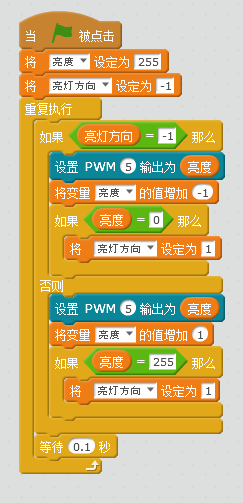
Digital signals are represented by 0 and 1, which indicate non-continuous changes in voltage levels, while analog signals represent information through continuously varying physical quantities, with signals changing continuously over time. Most of the signals we encounter in our lives are analog signals, such as changes in sound, light, and temperature. On our UnoR3 development board, pins 3, 5, 6, 9, 10, and 11 have PWM (Pulse Width Modulation pulse width modulation) functionality. By setting the PWM pins, a fixed period square wave is output on the specified pins through continuous switching between high and low levels. By changing the ratio of high and low levels in each cycle (duty cycle), different voltage outputs can be achieved. When the high level lasts longer within a cycle, the output voltage will be higher, and the LED will be brighter. When the high level lasts shorter, the output voltage will be lower, and the LED brightness will be dimmer.
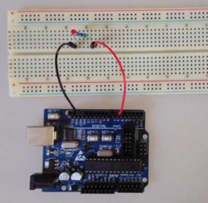
The connection method for this experiment can also refer to the introductory LED blinking. The LED has two legs, one long and one short; the short leg connects to GND, and the long leg connects to the positive terminal. A 220Ω current-limiting resistor needs to be added before the long leg of the LED. Since we need to control its brightness, the positive terminal must be connected to the port marked “~”, and we choose pin 5.
LED Breathing Light Program Schematic