The UJA1168 is a micro System Basic Chip (SBC) launched by NXP, available in multiple models, suitable for automotive ECU design. The main functions of this chip include:
-
CAN Transceiver
-
Supports CAN 2.0 (1 Mbps) and CanFd (2 Mbps)
-
Some models support “FD-passive” mode
-
Low Power and Partial Network Management
-
Supports Standby mode and Sleep mode
-
Supports Partial Network Management (Partial Network)
-
Power Management
-
Can provide an external power output of 5V/100mA (V1)
-
Some models can provide 5V/30mA sensor power (VEXT/INH)
-
System Control and Diagnostics
-
Access to built-in registers via SPI interface
-
Supports remote Flash programming (CAN bus)
-
Watchdog
-
Window/Timeout/Autonomous modes
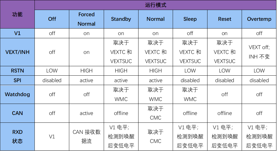
The UJA1168 offers various operating modes, with the functions or states of each module as follows (for detailed information, refer to the official NXP datasheet):
The switching logic between different modes is as follows:
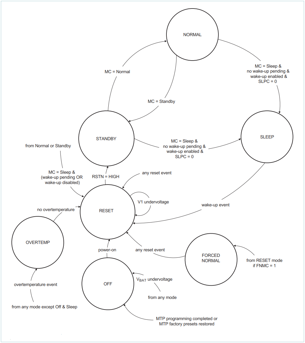
When leaving the factory, the UJA1168 is set to ForceNormalMode (FNMC=1) by default. In ForceNormalMode, SbcTrcv/CanSM may not be able to switch the SBC’s operating mode properly. Simply turning off ForceNormalMode will cause the SBC watchdog to reset. The correct approach is to exit ForceNormalMode during additional custom initialization when initializing the SBC and enter SoftwareDevelopmentMode (in this mode, the watchdog is off, and users can switch the SBC’s operating mode freely). Example code:
// Set V1 and INH/VEXT control register (addr. 10h)uint16 Reg10_req = 0x204F;uint16 Reg10_resp = 0x0;Sbc_xx_Uja1168_AccessRegister(0, Reg10_req, &Reg10_resp); // Parameter 0 indicates DeviceId, same below
// Set Start-up control register (addr. 73h)uint16 Reg73_req = 0xE638;uint16 Reg73_resp = 0x0;Sbc_xx_Uja1168_AccessRegister(0, Reg73_req, &Reg73_resp);
// Set configuration control register (addr. 74h)// Deactivate Forced Normal Mode via FNMC bit// Leave undervoltage detection at 60% and// set SDMC bit for developmentuint16 Reg74_req = 0xE834;uint16 Reg74_resp = 0x0;Sbc_xx_Uja1168_AccessRegister(0, Reg74_req, &Reg74_resp);
// write CRC to MTPNV register (addr. 75h) to accept the change// CRC8H2F for Reg73=0x38 and Reg74=0x34 is 0xCCuint16 Reg75_req = 0xEACC;uint16 Reg75_resp = 0x0;Sbc_xx_Uja1168_AccessRegister(0, Reg75_req, &Reg75_resp);
Note 1:
When accessing the registers ofUJA1168, the CMD instruction length is two bytes:
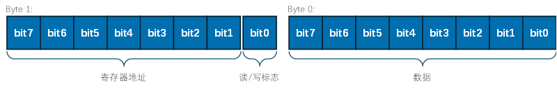
Where:
-
The high byte contains the address information of the register (bit7~bit1) and the read/write flag (bit0)
-
Address information: see the datasheet for details
-
Read/Write flag: 0 indicates writing to the register; 1 indicates reading from the register (at this time, the low byte data is ignored)
-
The low byte represents the data written to the register
-
When the read/write flag is 0 (writing to the register), the low byte data takes effect
Note 2:
After writing data to the Start-up Control register (73h) and Configuration Control register (74h), it is necessary to calculate the CRC of the values written to these two registers and write that CRC to the MTPNV CRC Control register (75h), after which the data in the above two registers will take effect. The CRC uses the CRC-8/H2F algorithm, with the algorithm parameters as follows:
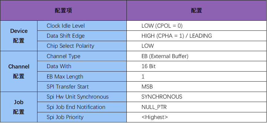
 Note 3:Several key configurations for SPI: