PDO stands for Process Data Object, primarily used for transmitting real-time data.
PDO is divided into Receive PDO and Send PDO, where the reference objects for “Receive” and “Send” are the slave devices. The Receive PDO refers to the data received by the slave from the master, such as control words and target positions; the Send PDO refers to the data transmitted from the slave to the master, such as status words and actual positions.
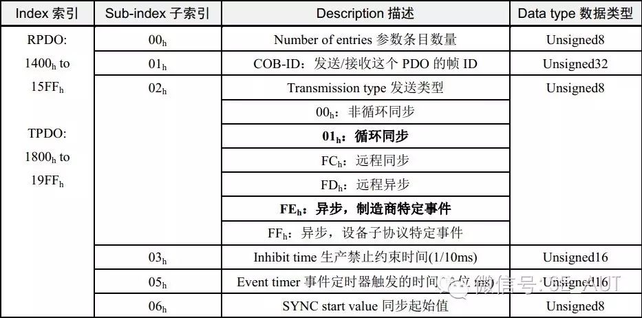
Each PDO is described by two objects in the Object Dictionary:
PDO Communication Parameters: which includes the COB-ID to be used by the PDO, transmission type, inhibit time, and timer cycle, etc.;
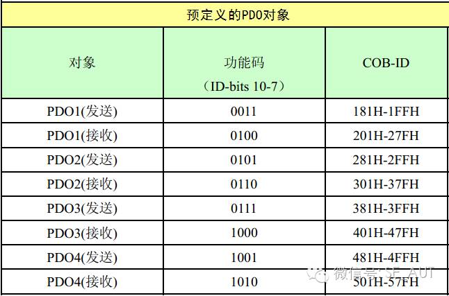
COB-ID Predefined (as per CiA301)
Transmission Type
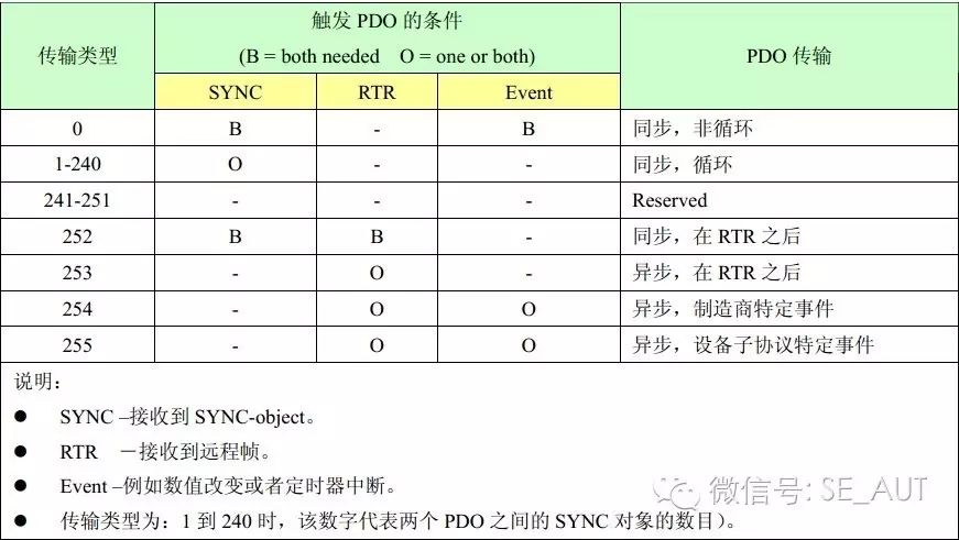
Synchronous Transmission:
Triggered by a synchronous message, divided into periodic and non-periodic
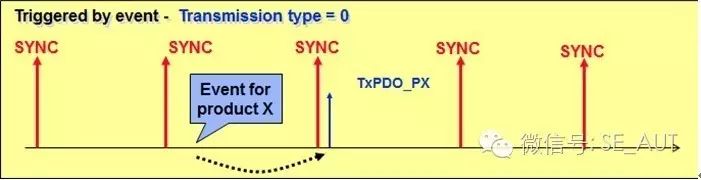
0: Non-periodic synchronous, transmitted upon receiving the first synchronous message as specified in the device sub-protocol’s specific event.
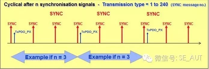
1-240: Periodic synchronous, transmitted every n synchronous messages.
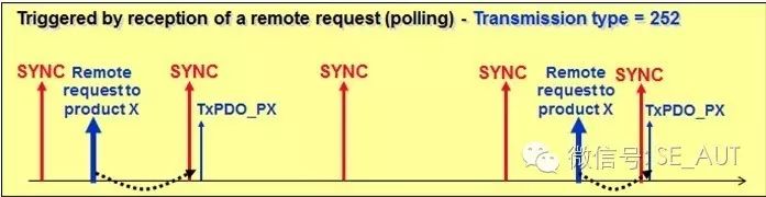
252: Synchronous, triggered by a remote frame, transmitted upon receiving the next synchronous message.
Asynchronous Transmission:
The first type is triggered by specific events defined in the device sub-protocol (e.g., timed transmission, data change transmission);
The second type is triggered by sending a remote frame to initiate the PDO transmission;
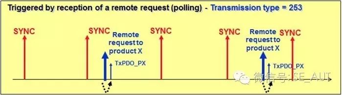
253: Asynchronous, triggering data exchange immediately upon receiving a remote frame without waiting for the next synchronous message.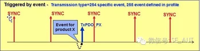
254, 255: Triggered by specific events designated by the manufacturer or defined in the device sub-protocol.
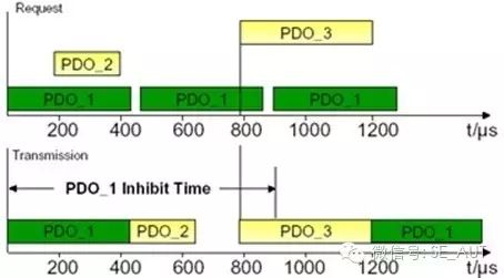
Inhibit Time: Defines the minimum interval time between two consecutive PDO transmissions to prevent high-priority data from monopolizing the bus, thus allowing low-priority data to be transmitted.
Event Timer: When the timer exceeds the set time, the PDO can be transmitted without triggering conditions; if this time is 0, it is event-triggered.
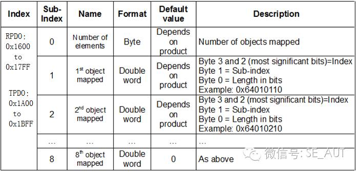
PDO Mapping Parameters: Contains a list of objects in the Object Dictionary that are mapped to the PDO, including their data lengths. The producer and consumer must understand this mapping to interpret the PDO content.
The above is an introduction to the CANopen PDO protocol, understanding this part is beneficial for better configuring PDO parameters when setting up CANopen slave devices.
Generally, CANopen devices will have predefined PDO configurations in their EDS files. When configuring CANopen slaves, PDO can be configured according to specific needs, with each PDO capable of exchanging up to 8 bytes of data.
Below are examples from different configuration software provided by Schneider:
Sycon
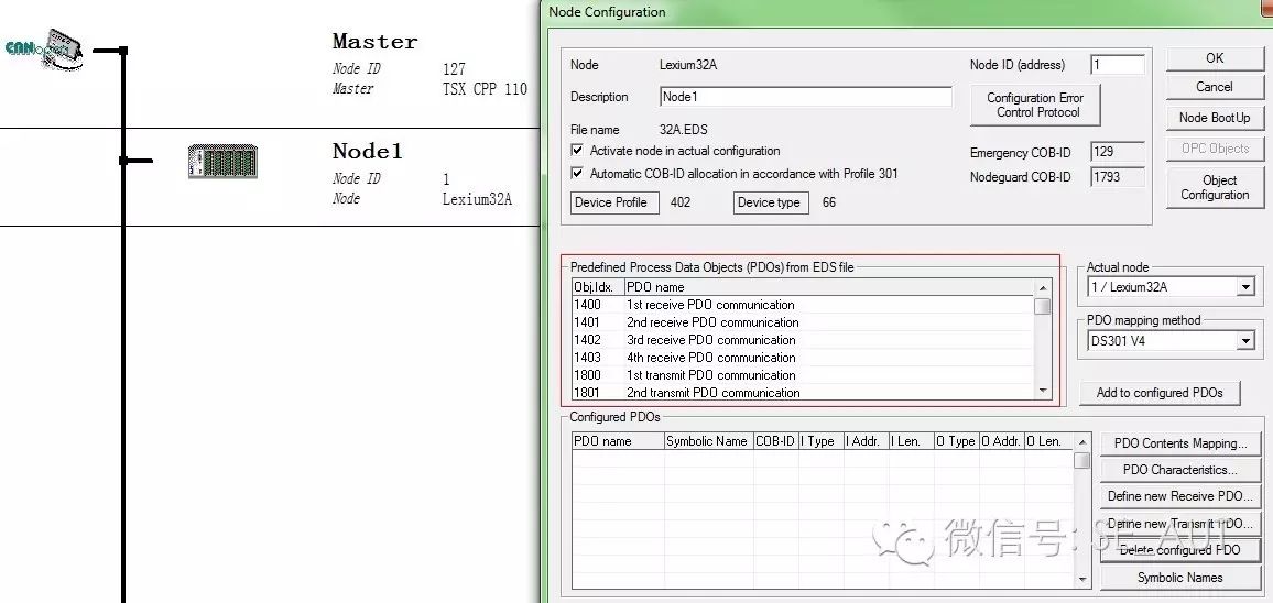
The content in the red box is four groups of PDO pre-set by the EDS file, and the corresponding PDO can be selected to load into the configuration box below;
Unity
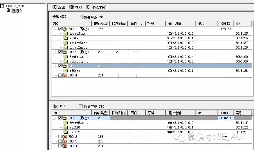
TPDO1 and RPDO1 are activated by default, and other groups of PDO can be selected for activation;
Somachine
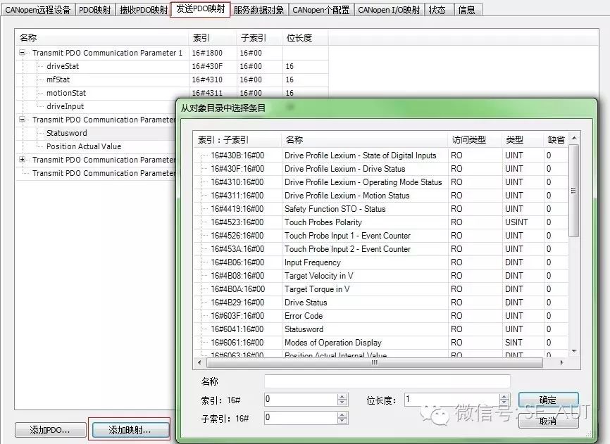 Mapping parameters in PDO can be added or deleted;
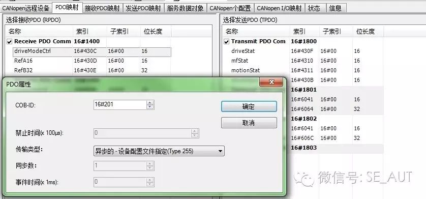
PDO transmission types, inhibit times, etc. can be configured..
Once the PDO is configured, its objects will be mapped to the registers of the master PLC. This method of exchanging data with the slave through reading and writing mapped registers is based on PDO communication.