1、Process Data Object (PDO) and Service Data Object (SDO) MessageID.
When using CANopen, the configuration information and application data that need to be transmitted are placed in the Process Data Object PDO (Process Data Object) and Service Data Object SDO (Service Data Object). These objects are like baskets of fruit sold in the market; they are the same size but contain different items (application data), as shown in the figure. This is the basic protocol defined by the CiA301 protocol – the “basket”, while the sub-protocols of CiA4xx or user-defined objects are the “contents” of the basket.
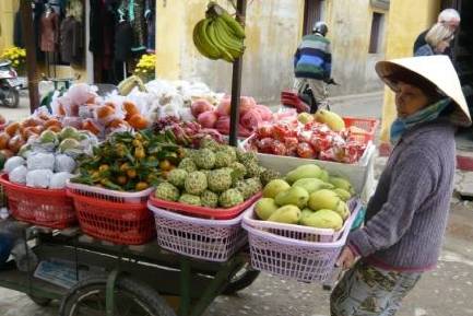
PDO and SDO are like fruit baskets.
PDO and SDO differ in communication; PDO is process data, meaning it is unidirectional and does not require the receiving node to respond with a CAN message to confirm receipt. From a communication terminology perspective, it belongs to the “producer-consumer” model.
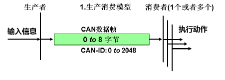
Producer-consumer model
On the other hand, SDO is service data, which has a specified address for the receiving node (Node-ID) and requires the specified receiving node to respond with a CAN message to confirm receipt. If no confirmation is received within a timeout period, the sending node will resend the original message. This communication method belongs to the common “server-client” communication model, which is typically referred to as polling. As shown in the figure.
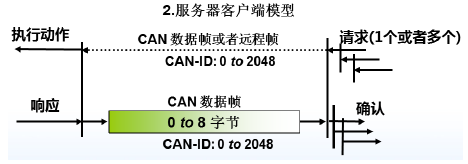
Server-client model
For the assignment of message IDs for PDO and SDO, in order to reduce the configuration workload of the network, CANopen has predefined a mandatory default identifier (CAN-ID) assignment table, which is based on the 11-bit CAN-ID standard frame format. It is divided into a 4-bit function code (Function-ID) and a 7-bit node number (Node-ID). As shown in the figure.
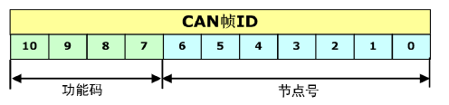
Predefined connection ID assignment for PDO and SDO
In CANopen, the CAN-ID is also commonly referred to as COB-ID (Communication Object Identifier). Thus, we can distinguish between the two easily confused terms:
COB-ID: Communication Object Identifier, which is the message frame ID of a certain communication object in CANopen, specifically the 11-bit ID of a CAN message, representing a communication meaning.
Node-ID: Node ID number, which is the address of a node in the CANopen network. CANopen specifies a logically maximum of 128 nodes, so Node-ID must be at least 128 (7 bits).
COB-ID and Node-ID are not inherently linked, but in the Process Data Object (PDO) and Service Data Object (SDO), the COB-ID contains the Node-ID.
Since it is necessary to distinguish between the input and output of each CANopen node, PDO is divided into TPDO (Transmitted PDO) and (Received RPDO), where transmission and reception are referenced to the CANopen slave node (if it is a CAN master, the reverse is true). TPDO and RPDO each have 4 data objects, each data object encapsulating 1 CAN message, as shown in the table. These are containers for data transmission and reception, just like the fruit basket shown above is prepared for the user; it depends on what the user puts in it.
On the other hand, SDO is relatively simple and fixed. The CAN frame ID for initiating communication with an SDO request is 600h + Node-ID, where the Node-ID is the address of the node being queried. The responding node’s SDO CAN frame ID is 580h + Node-ID. Generally, in a CANopen network, only the NMT master can initiate SDO communication for node parameter configuration or the transmission of critical parameters. Of course, slave nodes can also initiateSDO communication with other slave nodes.
As shown in the table, it defines the classification of PDO and SDO message IDs in the predefined messages of CANopen. Users must remember!
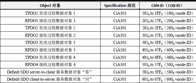
Definition of CAN-ID for PDO and SDO
2、Object DictionaryOD (Object Dictionary)
The CANopen Object Dictionary (OD: Object Dictionary) is the core concept of the CANopen protocol. The so-called object dictionary is an ordered group of objects that describes all parameters corresponding to a CANopen node, including the storage location of communication data, which is also included in its index. This table can be transmitted in the form of an EDS file (Electronic Data Sheet). The object dictionary is like a physical examination form, containing parameters for each function of this person, making it easier for employers (masters) to allocate work reasonably.
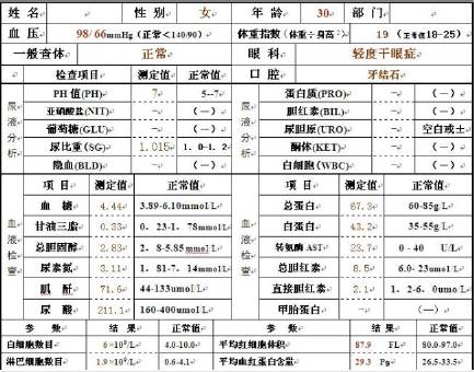
Object Dictionary and Physical Examination Form
Each object is addressed using a 16 bit index value, which is usually referred to as the index, ranging from 0x0000 to 0xFFFF. To avoid running out of indices when there is a large amount of data, an 8 bit index value is also defined under certain indices, which is usually referred to as a sub-index, ranging from 0x00 to 0xFF.
Each parameter within each index can be represented by a maximum of 32 bit variable, namely Unsigned32, which is four bytes.
Each CANopen device has an object dictionary, using an electronic data document (EDS file) to record these parameters, without the need to record these parameters on paper. For the master nodes in a CANopen network, it is not necessary to access every object dictionary item of the CANopen slave nodes.
The items in the CANopen object dictionary are described by a series of sub-protocols. Each sub-protocol describes the functionality, name, index, sub-index, data type of each object in the object dictionary, as well as whether this object is required, read-write attributes, etc., ensuring compatibility of similar devices from different manufacturers.
The core descriptive sub-protocol of the CANopen protocol is DS301, which includes the description of the CANopen protocol application layer and communication structure. Other sub-protocols are supplements and extensions to the description text of the DS301 protocol. A CANopen device sub-protocol is drafted for different application industries, and the sub-protocol number is generally DS4xx.
2.1 Overview of Object Dictionary
As shown in the table, it defines the index area of the object dictionary, where the communication object sub-protocol area and manufacturer-specific sub-protocol area marked with green background are the areas users need to focus on.
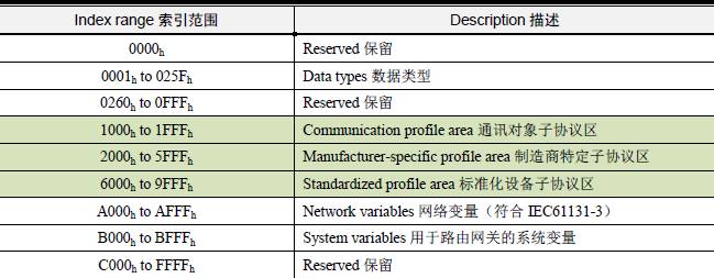
Overview of Object Dictionary
2.2 Communication Object Sub-protocol Area (Communication Profile Area)
The Communication Object Sub-protocol Area defines all object parameters related to communication. As shown in the table, the index range marked with a green background from 1000h to 1029h is for general communication objects that all CANopen nodes must possess; otherwise, they will not be able to join the CANopen network. Other indices are allocated and defined based on practical situations.
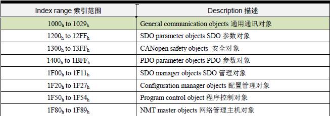
Communication Object Protocol Area
2.3 General Communication Objects
Due to the importance of general communication objects, the NMT master (CANopen master) usually reads all or part of the general communication objects’ indices from all slaves during startup. Therefore, all general communication objects must be implemented in the CANopen slave, and users must be familiar with these index addresses and their meanings.
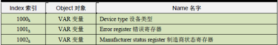
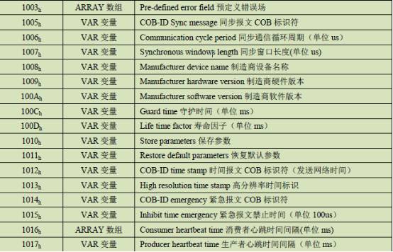
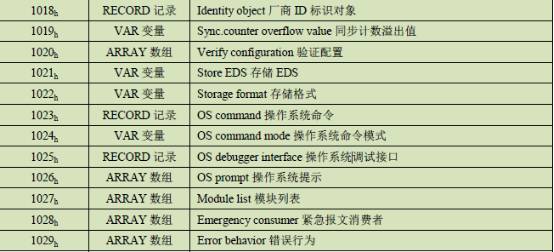
General Communication Objects
2.4 Manufacturer-Specific Sub-Protocol (Manufacturer-Specific Profile)
The object dictionary index from 2000h to 5FFFh is for manufacturer-specific sub-protocols, typically storing application data for the applied sub-protocol. The previously described Communication Object Sub-protocol Area (Communication Profile Area) stores the communication parameters for this application data. For example, the XGate-COP10 slave module from Guangzhou Zhiyuan Electronics specifies that:
The communication parameters for RPDO are stored in 1400h to 15FFh, while the mapping parameters are stored in 1600h to 17FFh, with data stored after 2000h in the manufacturer-defined area;
The communication parameters for TPDO are stored in 1800h to 19FFh, while the mapping parameters are stored in 1A00h to 1BFFh, with data stored after 2000h in the manufacturer-defined area.
Detailed explanations will be provided in the subsequent section on PDO (Process Data Object).
For special functions not defined in the device sub-protocol, manufacturers can also define object dictionary objects in this area according to their needs. Therefore, this area may have different definitions for the same object dictionary item among different manufacturers.
2.5 Standardized Device Sub-Protocol (Standardized Profile Area)
The standardized device sub-protocol defines object dictionary objects for various types of standard devices across different industries. Currently, there are over a dozen sub-protocols defined for different types of devices, such as DS401, DS402, DS406, etc., with an index value range of 0x6000 to 0x9FFF. Similarly, this area may have different definitions for the same object dictionary item among different standardized device sub-protocols. This part will not be discussed in this article.
This article is reprinted from Guangzhou Zhiyuan (original authors Zhou Ligong, Huang Minsi)