1. Overview
Based on the previous article titled “RT-Thread Device Driver Development Guide: Basics – Taking the HWTIMER Device of the First Paddle BSP as an Example” we can roughly understand the methods and steps for RT-Thread device driver development. The advanced peripherals covered in this guide are generally more complex than those in the basic guide, including SDIO, Touch, LCD, sensor, MTD nor, MTD nand, pulse encoder, encryption and decryption devices, and PM devices.
For the advanced peripherals, this article will not discuss the advanced peripherals already supported by First Paddle, but will instead provide a hands-on practice to drive an unsupported peripheral – LCD, to delve deeper into developing RT-Thread device drivers.
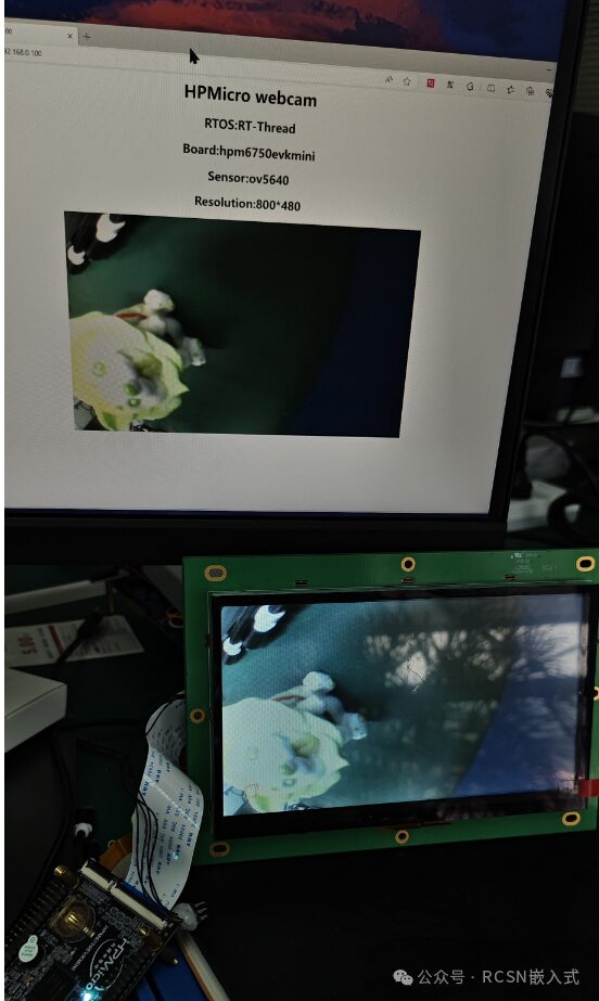
Let’s see the effect:
Add an LCD driver to display the camera feed based on the official example of wifi_web_camera_demo.
2. Development Method
(1) Introduction to RT-Thread’s LCD Driver Framework
The LCD driver is similar to other peripherals, primarily consisting of the IO device management framework -> LCD device driver framework -> LCD device driver.
The IO device management layer provides a unified operation interface for the device framework, including rt_device_read/write/open/close/control, etc. The ultimate goal of creating a peripheral driver is to use these unified operation interfaces in applications without concerning the underlying operations.
The LCD device driver framework layer is RT-Thread’s abstraction of the basic functions of the LCD. It is a general software layer independent of the hardware platform, abstracting the type definitions and specific operation methods of the LCD device. The framework source code can be found in rtdef.h.
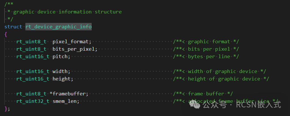
The information structure of the LCD rt_device_graphic_info defines pixel format, bit width, width and height, frame buffer address, etc.
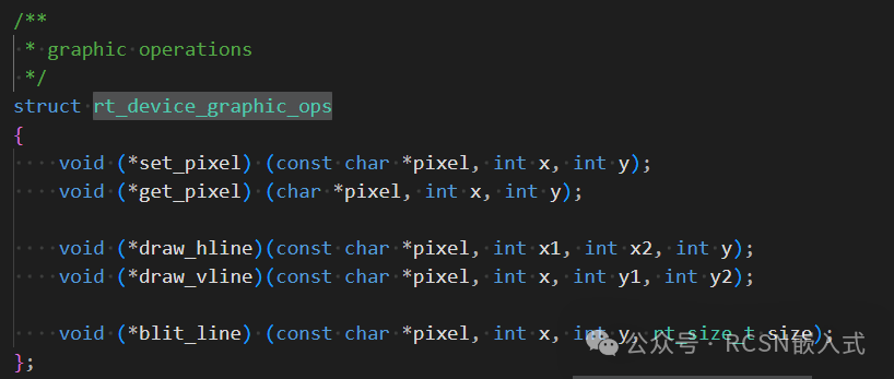
The operation interface of the LCD rt_device_graphic_ops defines drawing operations for the LCD, such as pixel points, lines, etc.
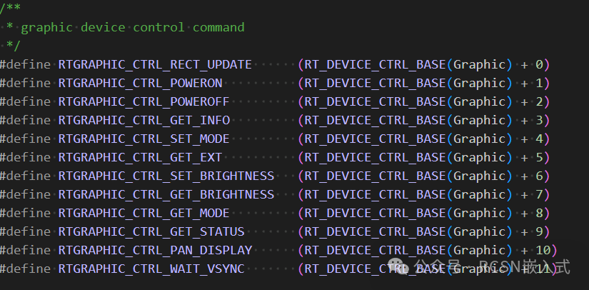
LCD control commands include updating the frame buffer, turning the LCD on/off, retrieving information, waiting for VSYNC, etc.
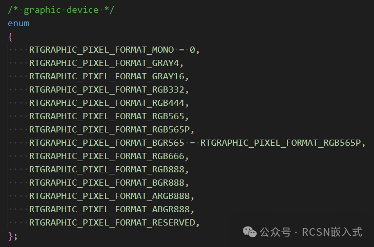
LCD pixel formats
As we can see, the abstraction of LCD operations in RT-Thread is quite intuitive. After completing the above operations, we can register the LCD using the IO device management layer’s registration interface rt_device_register, allowing us to operate the LCD using the IO device management interface.
(2) Introduction to First Paddle’s LCDC Peripheral
Regarding the hardware controller of First Paddle’s LCDC peripheral
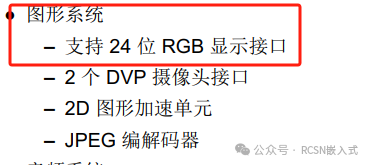
On the HPM6750, there is an RGB controller that supports a 24-bit RGB display interface.
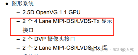
On the HPM6800, it supports two 4 Lane MIPI-DSI/LVDS-Tx display interfaces.
On RT-Thread, the hpm_sdk panel component is also supported, covering display adaptation for both HPM6750 and HPM6800.
For an introduction to the hpm_sdk panel component, please refer to the article “[hpm_application] Choose First Paddle! Smoothly Run 1080P or 720P MIPI Screens with Microcontrollers“
For screens communicating with the LCD hardware controller (RGB, MIPI DSI), the LCD device driver only needs to implement the operation methods of the LCD device struct rt_device_ops, such as updating the buffer of the hardware controller in the control interface to control screen drawing.
In this way, combined with the RT-Thread BSP adapted for First Paddle, it is easy to adapt the LCD driver, following the driver example from First Paddle’s BSP to create drv_lcd.

(3) Creating the LCD Device
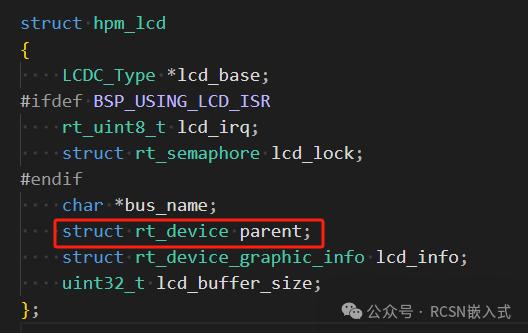
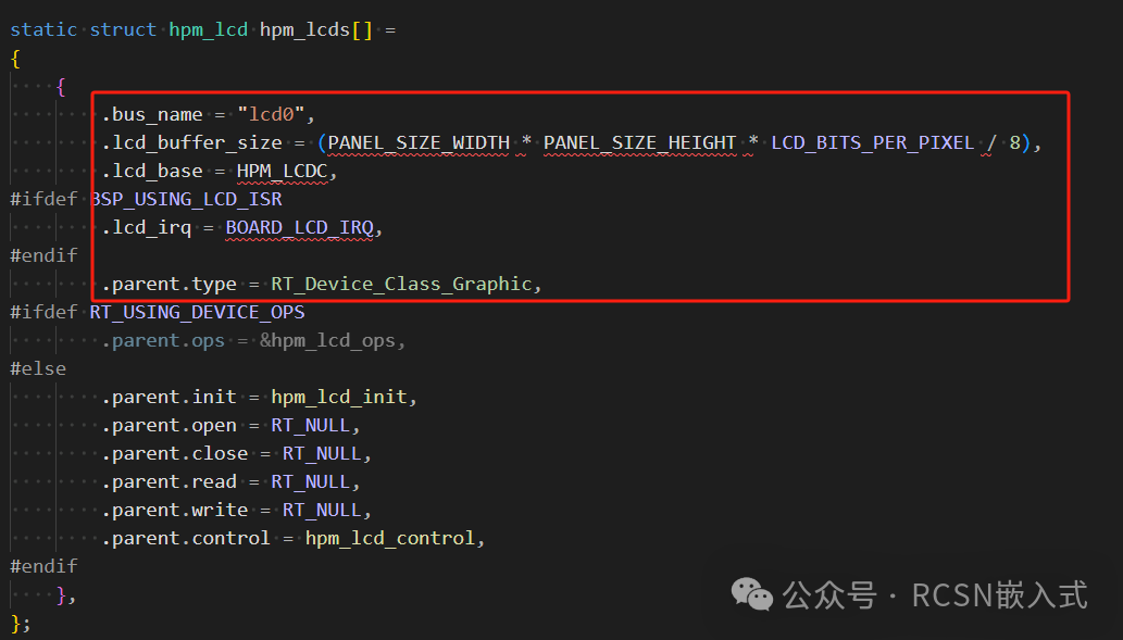
Now let’s create the LCD device for First Paddle. The LCD device model is derived from the struct rt_device structure and adds its own private data.
The members mainly include the base address of the LCD, interrupt number, mutex, LCD name, etc.
Instantiate an array of LCD devices, allowing for multiple LCD devices, containing the initialization parameters of the devices.
(4) Implementing the LCD Device Operation Methods
According to the above definitions, an hpm_lcd_ops structure has been instantiated, and we need to implement the corresponding operation functions, which are the operation methods defined for the LCD device. For the LCD device, only the init and control operation methods are meaningful, and this article implements these two interfaces: hpm_lcd_init and hpm_lcd_control.
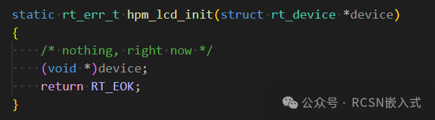
1. init: Initialize the LCD device
For this operation method, the LCD driver code for First Paddle does not need to perform any operations; it only needs to register and initialize the LCD.
2. control: Control the LCD device
The application can also control the LCD device through the control method. The prototype is as follows:
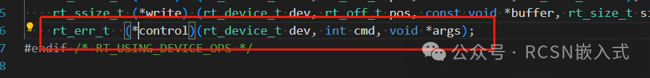
The parameter cmd includes the method to control the LCD, and the general device commands can use the following macro definitions:
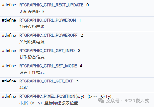
Of course, several commands were also updated in the latest version rtthread 5.0.2.
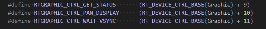
This article mainly implements the following commands:
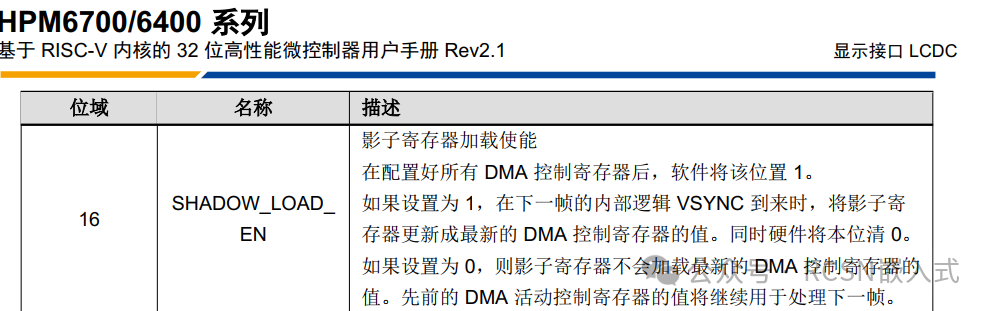
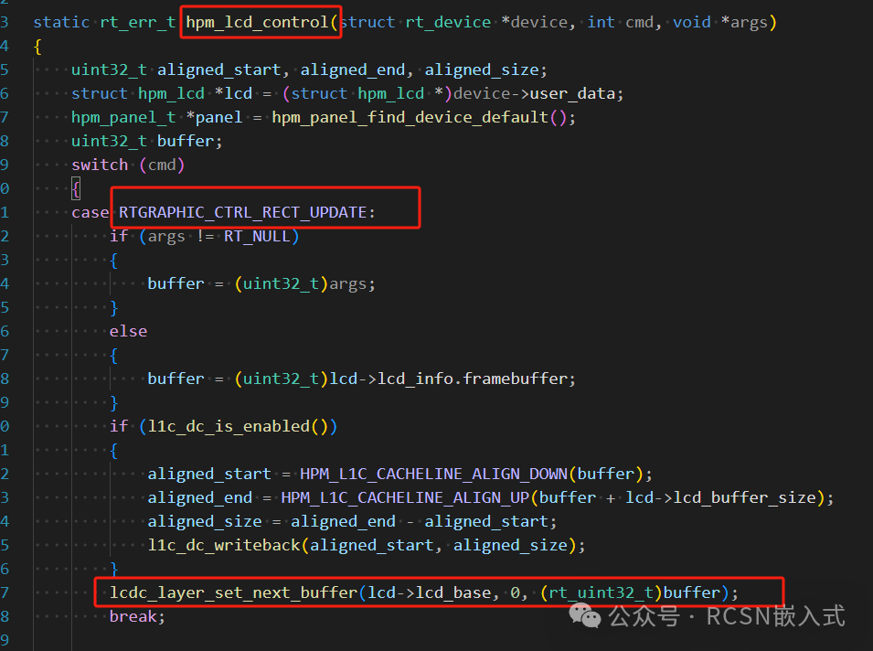
(1) RTGRAPHIC_CTRL_RECT_UPDATE: Update the frame buffer
For updating the frame buffer, you can use the frame buffer defined by the controller itself or the passed-in frame buffer address. The First Paddle manual mentions the shadow register loading enable function, meaning that the frame buffer will load on the next VSYNC arrival, allowing for complete display updates.
The hpmicro driver also provides this API: lcdc_layer_set_next_buffer, and the adapted driver uses the first layer.
Therefore, we can implement:
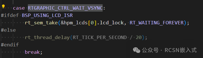
(2) RTGRAPHIC_CTRL_WAIT_VSYNC: Wait for frame completion
To ensure efficient transmission and prevent tearing, we use interrupt-based transmission for one frame, and wait for VSYNC to complete before updating the next frame.
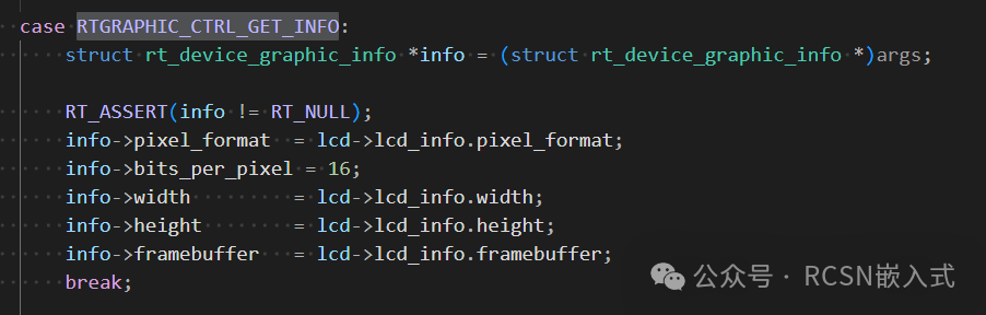
(3) RTGRAPHIC_CTRL_GET_INFO: Get LCD information
This mainly retrieves the LCD’s pixel format, width, height, etc., passing them to the args parameter.
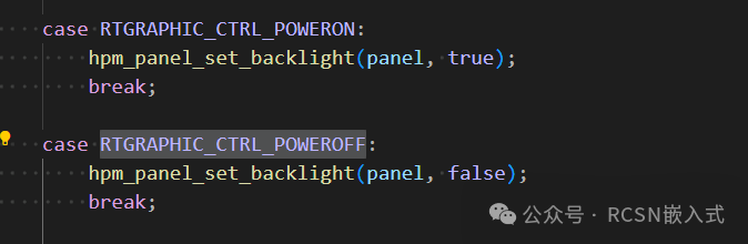
(4) RTGRAPHIC_CTRL_POWERON: Turn on the screen
RTGRAPHIC_CTRL_POWEROFF: Turn off the screen
Call the hpm_sdk panel component interface to achieve this.
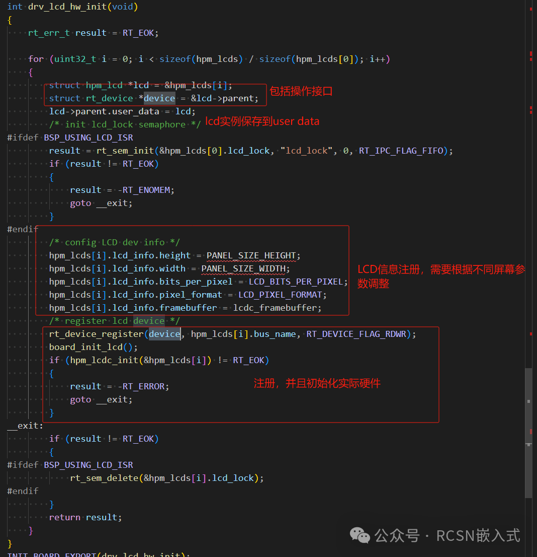
(5) Registering the LCD Device
Use the IO device framework’s rt_device_register to complete the registration, focusing mainly on the assignment of the device operation methods and saving the LCD device instance to the lcd’s user_data member.
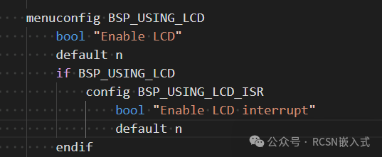
(6) Driver Configuration
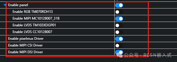
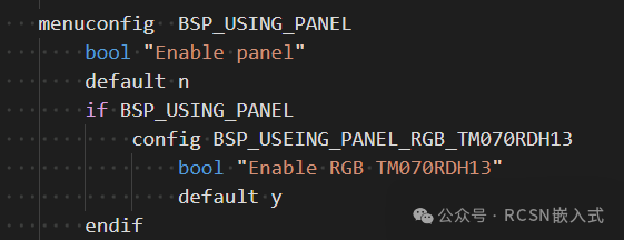
Enable the LCD in the board’s Kconfig, which controls whether the LCD driver-related code is added to the project.
Additionally, add the panel component. This macro has already been implemented by First Paddle, so only the RGB interface is available for HPM6750.
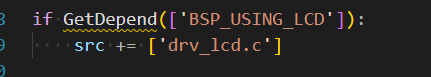
Add the LCD driver judgment option in the drivers’ SConscript file. If enabled, drv_lcd.c will be added to the project.
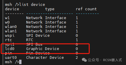
(7) Driver Verification
After registering the device, the LCD device will appear in the IO device manager. We use the official example wifi_web_camera_demo on the HPM6750EVKMINI for verification. After burning the program, we use the list device command to see that the registered device includes the LCD device.
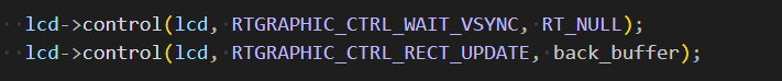
In the example of wifi_web_camera_demo, we add the LCD device operation in the interface that retrieves the camera image, displaying the image on the LCD. We just need to open the LCD and then execute control; two statements can achieve the display, making it particularly convenient to operate.
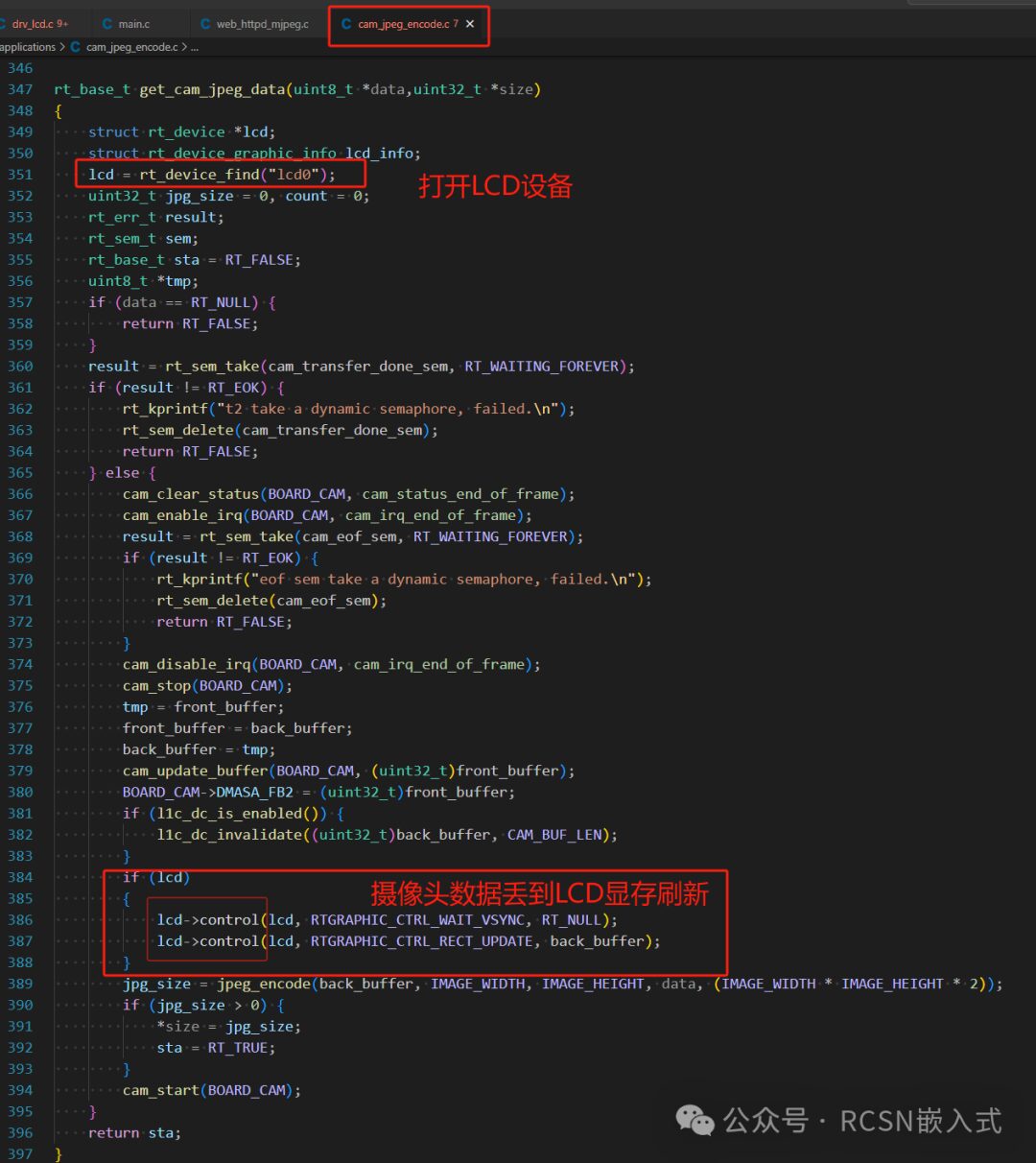
Ultimately, we can operate the LCD using simple IO device operations.
———————End———————

👇 Click to read the original text and enter the official website