
In this article, we will briefly understand the device drivers in VxWorks and complete the reverse analysis of the entire firmware main logic, while reproducing the last known vulnerability of the firmware.
This article was actually written a long time ago, but was delayed for several days due to the Shandong Provincial Competition… I apologize to everyone. This will be the concluding part of the Schneider NOE77101 firmware. After this, I will analyze other firmwares. Of course, as I continue my learning, I may also add some details to this firmware. It is recommended to read other reverse engineering articles in the column first:
https://www.anquanke.com/subject/id/187300

During the reverse engineering process, we often encounter functions like xxxCreate, xxxDrv, iosDrvInstall, etc. These are actually operations on devices, or more precisely, operations on devices and their drivers. In the previous article, we explained in detail the special network drivers in device drivers. In this article, we will briefly introduce the other drivers. Of course, we are only doing this for convenience in reverse engineering, not for writing drivers. Those interested in writing drivers can look up relevant materials.
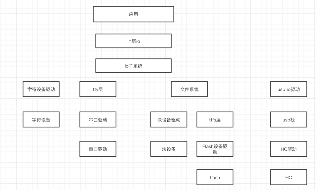
The upper layer IO here mainly refers to the interfaces we frequently use, such as open, write, etc., which have completely departed from the lower layer. The IO subsystem acts as a distributor and abstraction layer, further distributing read and write operations for different devices and providing convenient interfaces for the upper layer after abstracting operations. Below is the specific driver.
First, we have the character devices, which are devices that read and write data in byte stream format. For example, the keyboard we commonly use belongs to this category, and interfaces like I2C, SPI, UART can also be used as character device drivers. Character devices are limited by the byte stream read and write method, allowing us to easily handle data (coming one by one, operated in sequence each time), so VxWorks does not provide an intermediary layer for us, and we directly write the driver to operate the device.
Serial devices, in fact, the concept of serial ports is very broad. In the driver part of VxWorks, serial ports refer to “serial ports other than a few special types.” Due to the wide variety and differences of these devices (serial devices are widely used, but their usage varies), VxWorks has set up a tty intermediary layer. When we send data to the device, the IO subsystem does not process our data but forwards it to the tty intermediary layer, which then finds the corresponding driver to handle it. At this point, you may notice that the serial device driver should be “recognized” by the tty layer; otherwise, how can tty find the driver? This is actually a registration process, involving functions like ttyOpen, ttyDevCreate, etc. The first registered device is often treated as the standard input/output (do you remember that we had to change the standard input/output in the analysis process before we could perform printf operations?).
Block devices, such as hard drives, are typical block devices that read data in blocks. We often build file systems on them to operate the devices (like Windows’ NTFS, FAT, Linux’s ext4, etc.). VxWorks mainly provides two types of file systems:
-
dosFs, which is compatible with the MS-DOS file system, where the file structure we see resembles that of Windows.
-
rawFs, which does not process the data, treating an entire block of hard drive as a single file.
Flash devices are a type of non-volatile flash memory technology that we often use to store code (especially in the embedded field; if you have done IoT development, you must be familiar with it). It actually still belongs to block devices, but due to its wide applicability, uniqueness, and importance (widely used, storing code, and having different erase methods compared to hard drives), VxWorks has added an extra intermediary layer under the block device file system—TFFS (True Flash File System).
USB devices are quite troublesome because they often require coordination between both sides (for example, a USB flash drive, which also requires hardware, drivers, and software systems inside, and must coordinate with the host to achieve data transfer). We need to adapt to both hardware and software. Below is the abstract structure of USB devices:
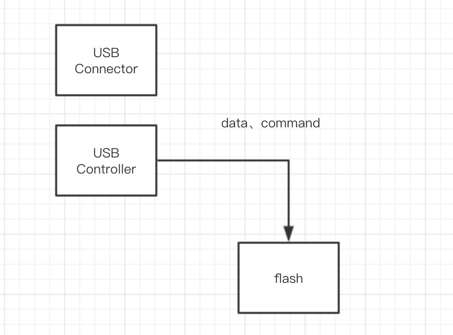
If we assume that we insert a USB flash drive into the device, it is like the two USB devices in the above diagram exchanging data. Clearly, what needs to be done well is the connection work and USB control work. We do not need to consider the connection; it mainly involves the controller. We need to write the driver for the controller and then establish a USB stack above it, thus completing the entire USB driver work.
For VxWorks, we often see operations on devices (such as xxxDevVCreate). In fact, these are all about establishing a connection between the device and the operating system, which is the process of building the model shown above. Generally, it requires:
Creating the device—Device initialization—Using the device
During the creation process, different devices include registering the device with the IO subsystem, establishing file systems, etc. Initialization includes optional initializations, basic settings, etc. We will see specific code during the reverse engineering process.

We continue from last time, entering usrAppInit for the next step of analysis.
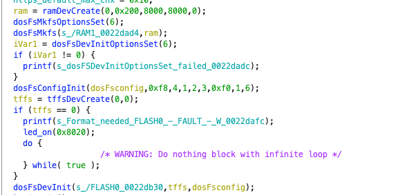
First, various initializations are performed, starting with creating a RAM device, which is the block device we mentioned above, and then establishing a file system in RAM1, initializing related settings. Then, a TFFS device is created, which is the flash device. Since we will later read important files such as running programs and configuration information from the flash device (which will be mentioned later), serious consequences may arise if the establishment fails, so if it fails, we will enter a dead loop.
Next, we reach the FTP_User_Add function. We enter to view it. Here, for the sake of clarity, I have modified the variable names.
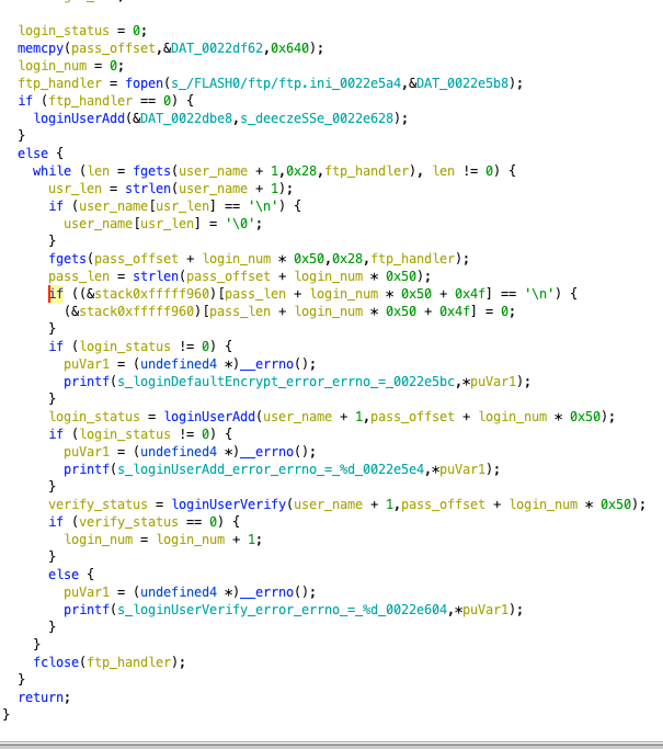
We can see that it first opens the /FLASH0/ftp/ftp.ini file. If it fails, it adds a default account (which means if the user has not set the ftp.ini, we can log in through this backdoor user directly). Then it sequentially reads the username and password from the ini file, and finally adds and verifies them. If an error occurs during this process, it prints the relevant error, but there is no setting check, so even if an error occurs, it will not cause problems for the system.
After reading the ftp ini file, it will perform ftp initialization operations. Although this is an API provided by VxWorks, there are many interesting aspects hidden inside, so let’s take a look.
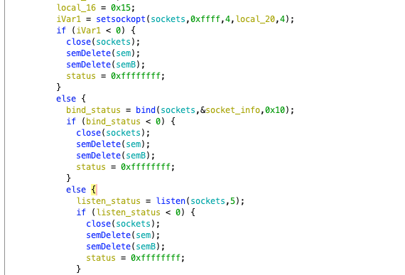
It starts by creating a socket and setting options for the socket, performing bind, listen operations, etc. Of course, it also involves a bunch of semaphore operations to ensure synchronization and mutual exclusion. Essentially, it implements the basics of network communication.
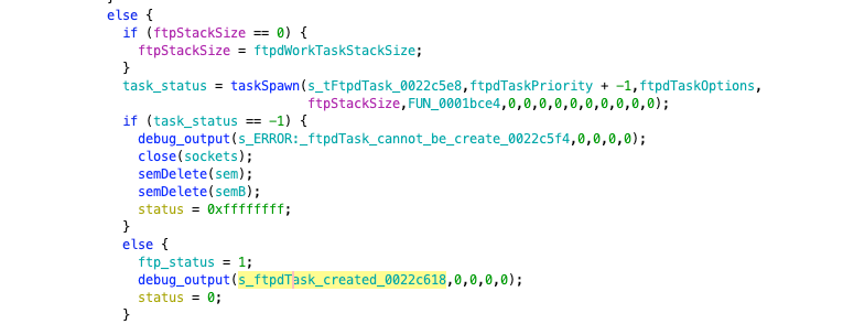
Then it calls the taskSpawn function to create a new task. We have mentioned this function before; the sixth function is the “main” function of the newly created task. If the call fails, it outputs an error message for debugging. From here, we will have to deal with “multithreading,” and the reverse engineering work will be slightly more complicated.
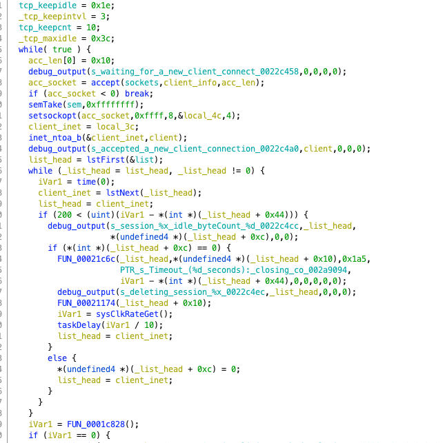
We can take a quick look inside. First, there’s a bunch of variable initializations, including common options like keepintvl, keepidle, etc., which are important options in TCP transmission. Below is a large while loop, which contains another loop. Following the general idea of reverse engineering loops, we first find the loop variable. Here, the first loop is an infinite loop, but in the inner loop, list_head is continuously iterated using lstNext, and client_inet is also equal to list_head, iterating synchronously. Each time client_inet is obtained, it undergoes certain processing.
In the outer loop, it first outputs a debug message indicating that it is waiting for user connections. Then it performs an accept operation using client_info as the socket connection object (we won’t elaborate on socket programming here). It then converts the client’s IP into a familiar format for debugging output, and then proceeds to the inner loop for the next step. At this point, we have a general understanding that this is the FTP connection operation. Further analysis will not be elaborated here, after all, we are focusing on industrial control, not protocol analysis.
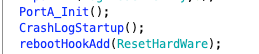
Continuing, PortA_Init is used to initialize the port, CrashLogStartup is for log settings, rebootHookAdd is the hook operation we mentioned earlier, which hooks the reboot operation, and resetHardWare is the function after the hook, which mainly involves some setting operations. Returning to usrAppInit, the next call is the bpi_init function.
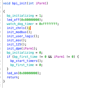
It turns off the light, initializes a bunch of things, turns the light back on, and is quite straightforward. Among them, there is the initialization of modbus that we are quite familiar with. Additionally, eos is worth noting, and 125 is a “special case.” We will look at these things later. Then back to the “main” function.
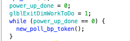
It sets power_up_done to 0, then loops to execute the new_poll_bp_token function. power_up_done will change within that function (we can check through cross-referencing), so this is not an infinite loop; let’s enter that function.
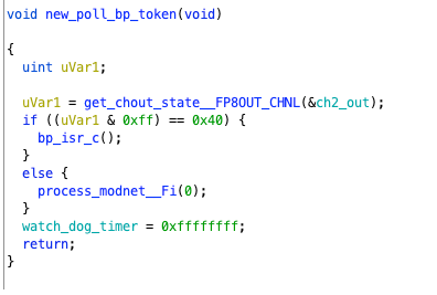
It first obtains the state of channel 2 out and performs a bitwise AND operation with 0xff to check if the result is 0x40. This is a common technique in hardware programming. 0x40 corresponds to 0000 0100, and the AND operation checks whether the third bit of state is 1. If it is, it enters bp_isc_c; if not, it calls process_modnet. We will first look at the case where it is not.
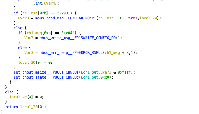
It first obtains information from channel 1 out, then performs a series of timing operations, and finally outputs the time when the modnet command was received. Then it checks the 0xb position of the content of channel 1. If it is 0x03, it reads the information; if it is 0x04, it writes the information. Here, we will select reading information as an example, noting that the parameter passed in is msg+8 (which we will use msg_8 to represent below).
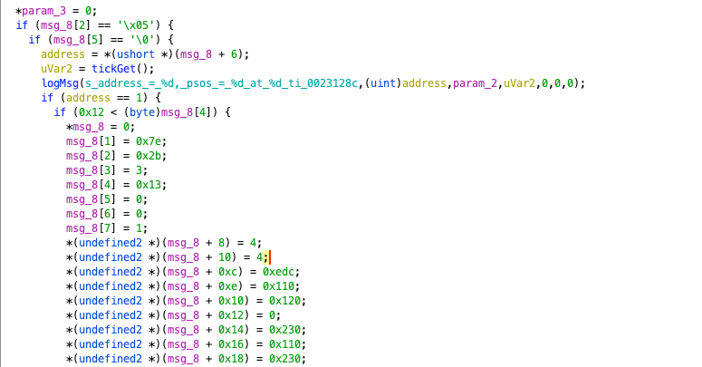
It checks whether msg_8’s 2nd and 5th positions are 0x5 and 0x00, respectively. If not, it directly calls mbus_err_resp__FP9ERROR_RSPUc, returning a fixed value of 0xd. If they are, it takes msg_6 as the address and uses the tickGet function to get the time, printing the relevant information. Then it performs different operations based on whether the address is 1 or 3, mainly a series of assignments. If it is 1, it returns 0x38; if it is 3, it returns 0x18.
Returning to new_poll_bp_token, this time we enter the bp_isr_c function for research.
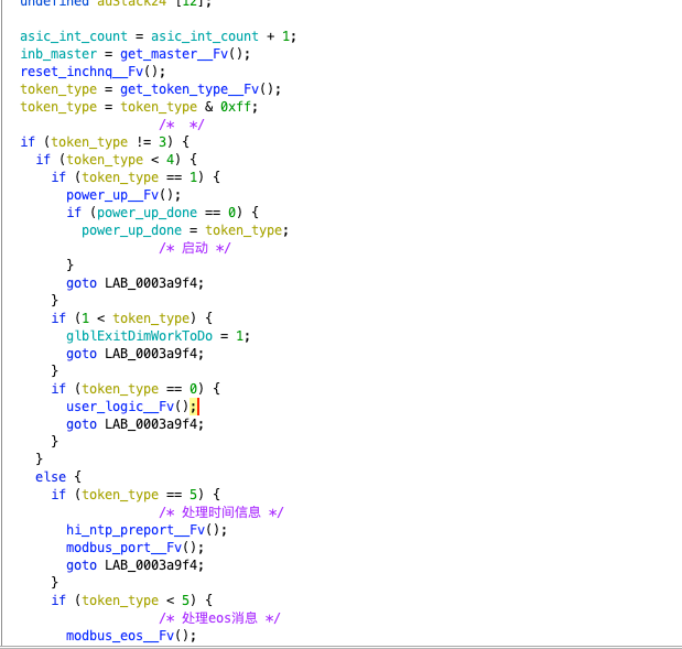
We can see that the program dispatches processing based on the token’s type. Note that power_up_done will be set to 1 due to token_type=1, breaking the previous while loop. This involves multiple logics, including modbus, eos, user_logic, etc. To write all of this down would probably take several articles, so we will choose to analyze just the part that processes modbus messages. Those interested can try analyzing it themselves.
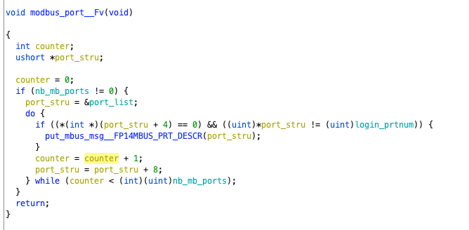
It first checks whether nb_mb_port is 0. This variable represents the number of ports. If not, it obtains the list of ports, looping through them. The loop variables are counter for counting and the port structure. The loop content checks whether the fifth item of port_stru is 0 and whether the first item is not login_prtnum (which starts empty and later changes). If it matches, it calls put_mbus_msg with the port structure as a parameter.
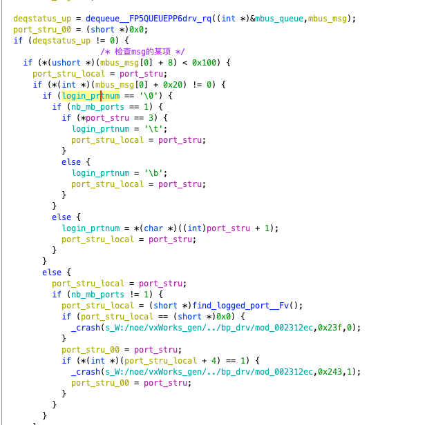
This function first retrieves various msgs from the mbus_queue using the dequeue function. The operation is similar to a linked list, where [0] of mbus_queue indicates the number of subsequent msgs, and [1] points to the next node. The dequeue function assigns [1] to mbus_msg, then makes mbus_queue’s [1] point to the next node, effectively traversing the msgs. Note that there is no loop, as the looping process occurs in the outer function.
It then checks whether msg[8] is less than 0x100. If not, it directly treats it as invalid information. Then follows a series of checks; regardless of the outcome, we ultimately assign the incoming port structure to a local variable.
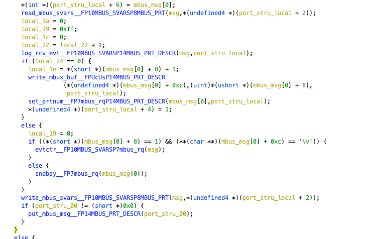
Next, we set the sixth item of our port structure to msg[0], and then access memory using the read_mbus_svars function, retrieving content and assigning it to msg. The remaining operations are rather tedious, mainly storing the message elsewhere without further processing. Then, we recursively call the function using port_stry_00 as a parameter.
At this point, we have completed the modbus_port_FV function. Returning to bp_isr_c, this function contains a large number of message processing functions, but due to space limitations, we will not delve further into it. It is recommended that everyone continue their research. Now, let’s go back to the “main” function.
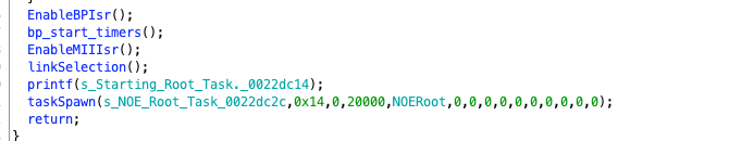
The next few functions are also used for initialization tasks. Once all of these are completed, it prints “Starting Root Task.” and then creates a new task named NOERoot through taskSpawn.
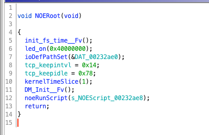
This task will first turn on a light, then initialize the Device Manager, create a new DM task, and execute the user-specified program.
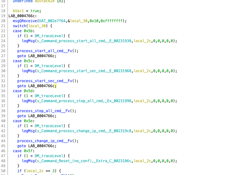
The task created by DM will read messages and perform operations such as stopping all commands, restarting, etc. It can be said to have similar authority to Linux’s root permissions.
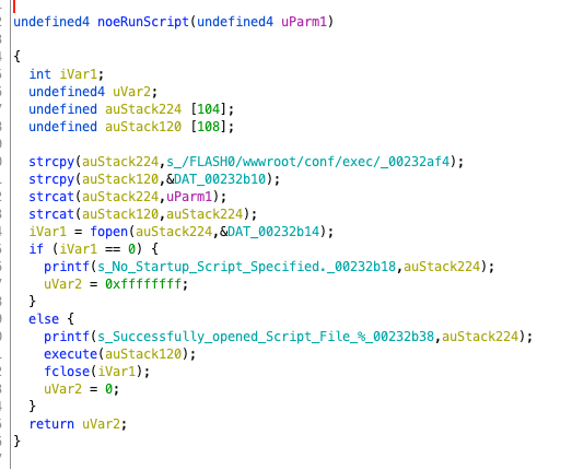
Firstly, it copies a path, then concatenates NOEScript, opens it, and if successful, executes that file, which means that this file contains the specific operations that follow. Thus, we have completed the exploration of the main logic of the entire firmware, from the initial boot and light activation to the final root access. We have basically covered everything, although there are many places we have not analyzed. Interested students can continue to explore.

We have reproduced two vulnerabilities earlier; in fact, this firmware has a total of three CVEs. However, since the third CVE does not appear in the main logic, we did not encounter it during the reverse engineering process.
CVE-2011-4861 has a vulnerability in the modbus_125_handler function within the Schneider Electric Quantum Ethernet module. Remote attackers can exploit the MODBUS125 function code on TCP502 to install arbitrary firmware updates. It is written simply, so let’s take a closer look at what exactly is happening.
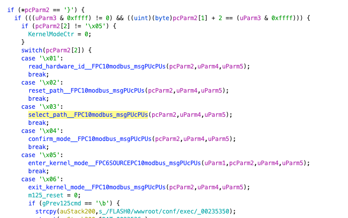
First, it checks whether the function code of the received message is 125. If it is not, it sets board_id to 0x1. If it is, it uses a switch statement to dispatch based on code[2], which represents the sub-function code, including operations like reading hardware ID and entering kernel mode, which are highly privileged operations. However, this alone does not pose too much danger; the real issue lies in the subsequent content.
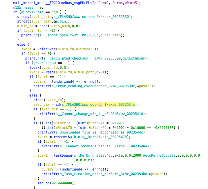
When it checks that the sub-function code is 6, it examines whether the instruction is 8. If so, it performs the following operations: first constructs a string for the directory of a.bin, tries to open it, and if successful, performs a legality check. Then it reads the header of the file; if it fails, it reports an error. Next, it attempts to enter the /FLASH0/wwwroot/conf/exec directory. If successful, it performs a simple check to see if the file is the downloaded kernel bin. If so, it renames a.bin to newkernel.bin and finally creates a kernel update task, turning on the LED light.

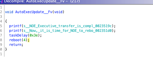
The update task simply prints a prompt message, delays the task, and then reboots. It can be seen that throughout the entire process, there is no strict user verification or firmware verification. We only need to perform simple processing on the firmware and construct traffic packets to replace the device firmware, leading to device paralysis or flashing a vulnerable firmware version for further attacks.
- End -

Recommended Reads
【Technical Sharing】Learning Notes: UAF Reuse After Release

【Technical Sharing】Decoding Windows Protocols from Mimikatz

【Technical Sharing】Decoding Windows Protocols from Mimikatz


Click "Read Original" for more content