The English terms on circuit boards, in addition to letters and numbers representing component numbers, also include some signal annotations such as VCC, VDD, GND, etc. We often see these English terms on circuit boards, but what do they mean? Let’s decode them together.
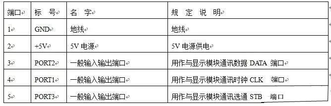
Before that, let’s familiarize ourselves with the letters representing commonly used components. The rule is that letters plus numbers indicate the component number, for example, R100 indicates a resistor numbered 100. Here are some commonly used ones.
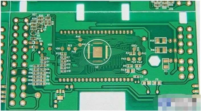
Resistors are represented by R.
Capacitors are represented by C.
Inductors are represented by L.
Transistors or field-effect transistors are generally represented by Q or VT.
Integrated circuits are generally represented by U or IC.
Voltage regulators are commonly represented by ZD.
Ordinary diodes are represented by D.
Switches are represented by SW.
Crystal oscillators are represented by Y.
Unidirectional thyristors are represented by SCR.
Bidirectional thyristors are represented by TRIAC.
Potentiometers are generally represented by RP.
Fuses are represented by FUSE.
Rectifier bridges are represented by DB.
Motors are generally represented by M.
Transformers are generally represented by T.
Thermistors are generally represented by RT.
Of course, there are many more; this is just what I can think of for now. Next, let’s see what the English terms for signals represent.
VCC generally represents the power supply voltage.
VDD generally represents the chip operating voltage.
VSS represents the low potential end of the power supply.
GND is the ground terminal.
CLK represents the clock signal.
CS represents the chip select signal.
EN is the enable terminal, which is a switch control.
RX represents receiving data, which is present in USB cables.
TX represents transmitting data.
RESET means reset.
The above are just a few common signal identifiers; these signal identifiers are usually found at the interface of the circuit board. The image below shows a definition of a power interface.
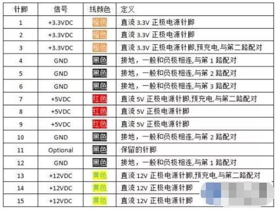
There is a set of specifications for defining various interfaces. Generally, manufacturers will design according to interface definition specifications, but they may also label according to the personal habits of engineers. For example, in USB interfaces, the red power wire may be labeled VCC, POWER, or 5V, but they all mean the same thing. If you encounter a more individualistic developer and want to understand the various labels of a product, you can only ask them.
Various circuit boards have their own different markings, and there are also common markings that indicate the manufacturer and the type of circuit board usage and product number, which require checking the corresponding product manual. Common universal markings include: GND for ground, Vcc (including Vcc1, 2 or Vcc3, 3.5, 12, etc.) for positive power and voltage levels, AC for alternating current, DC for direct current, |N for input terminal, 0ut for output terminal, |C for integrated circuit chips, G for bipolar transistors, D for bipolar diodes, c for capacitors, R for resistors, L for inductors, B for transformers, cx for sockets (plugs)… These are commonly used symbols that should be remembered without checking the book; for inaccuracies, please refer to the materials.


To help everyone learn better, Changxue Electronics has specially added a public account for microcontrollers and EDA, pushing relevant knowledge daily, hoping to assist your studies!