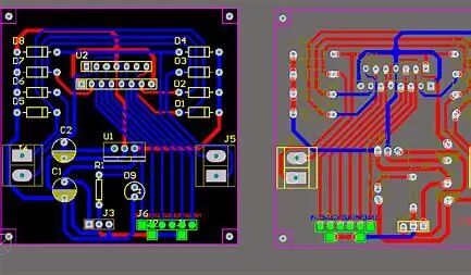
PCB Circuit
Advanced Schematic Design
The advanced design of PCB schematics requires integration of engineering practices, signal integrity, design specifications, and advanced tool functionalities.
1.Modular and Hierarchical Design
Modular Segmentation: Divide complex circuits into independent modules based on functionality (such as power supply, MCU, communication interfaces) for easier reuse and maintenance.
Hierarchical Schematics:
Use hierarchical symbols (SheetSymbol) to create top-level block diagrams that link to sub-schematics (supported by tools like Altium Designer, Cadence, etc.).
Implement signal interaction between modules through ports (Port) and off-sheet connectors (OffSheetConnector).
Design Reuse: Save validated modules as templates to reduce repetitive design work.
2.Signal Integrity (SI) and Power Integrity (PI)
High-Speed Signal Design:
Label the impedance requirements for key signals (such as clock, differential pairs) (50Ω/90Ω/100Ω).
Use differential pair (DifferentialPair) symbols to clarify length matching rules.
Power Network Optimization:
Label the current carrying capacity of power rails (such as 3A@5V).
Plan decoupling capacitor layout: high-frequency capacitors close to chip pins, low-frequency capacitors at power entry.
Reference Design Learning: Refer to the evaluation board schematics from chip manufacturers (such as TI, Xilinx), to learn key circuit designs.
3.Design Specifications and Maintainability
Naming Conventions:
Signal names reflect functionality (such as I2C_SCL, USB_D+).
Power network naming distinguishes voltage (such as +3V3_AUDIO, +5V_DIGITAL).
Annotations and Labels:
Add design notes (such as “This section should be away from RF modules”).
Label key parameters (such as resistor power rating, capacitor voltage rating).
Version Control: Use Git or SVN to manage schematic versions and record modification logs.
4.Simulation and Verification
Circuit Simulation:
Use SPICE tools (LTspice, PSpice) to verify the performance of analog circuits (such as operational amplifiers, filters).
Simulate load transient response for power circuits.
Signal Integrity Pre-analysis:
Label transmission line parameters in the schematic (such as microstrip, stripline structures).
Use HyperLynx, Sigrity and other tools to predict signal reflection and crosstalk issues.
5.Advanced Component Design
FPGA/Processor Systems:
Clearly define pull-up/pull-down configurations for unused pins.
Plan configuration circuits (such as Flash boot modes, JTAG interfaces).
Interface Protection Circuits:
ESD protection devices (TVS diodes) should be placed close to interfaces.
Add common mode chokes and filter capacitors (such as USB, Ethernet interfaces).
BGA Package Design:
Label the routing order and blind/buried hole planning.
Define decoupling strategies for power /ground pins.

6.EMC/EMI Design Considerations
Filter Design:
Add a π-type filter at the power entry.
Reserve positions for ferrite beads (FerriteBead) and filter capacitors for high-speed signals.
Grounding Strategy:
Distinguish between analog ground (AGND) and digital ground (DGND), and label single-point connection locations.
Use ground via arrays in high-frequency areas.
7.Design for Manufacturing and Testing (DFM/DFT)
Test Points (TestPoint):
Reserve test pads for key signals.
Label test points to prohibit covering with solder mask.
Assemblability:
Leave thermal relief annotations around high-heat components.
Ensure uniform direction for polarized components (such as electrolytic capacitors).
8.Advanced Tool Features
Altium Designer:
Use ParameterManager to manage component parameters uniformly.
Utilize MultiChannelDesign for rapid design of repeated modules.
OrCAD:
Manage different configuration versions through DesignVariants.
Use CrossReference to automatically generate signal cross-reference tables.
By employing these methods, the readability, manufacturability, and signal reliability of schematics can be significantly improved, while reducing the complexity of subsequent PCB layout and debugging. The ultimate goal is to achieve “schematic as documentation”—guiding subsequent development without additional explanations.
END