Introduction
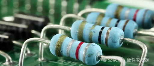
Resistors are one of the most fundamental components used in printed circuit boards (PCBs). They are passive devices that impede the flow of current in a circuit. PCB resistors can control, divide, stabilize, and connect circuits, among other functions. They come in various resistance values, sizes, power ratings, and tolerances to meet different circuit requirements.
The resistance value (measured in ohms) indicates the opposition to current flow. Resistors obey Ohm’s Law, which states:
V = IR
where V is the voltage in volts, I is the current in amperes, and R is the resistance in ohms.
Thus, for a given voltage, a higher resistance results in a lower current. Resistors convert electrical energy into heat, which must be dissipated. They are purely passive devices and cannot amplify or increase power.
Why Use Resistors in PCBs?
Here are some primary applications of resistors in PCB circuits:
Current Limiting — Resistors prevent damage by limiting the current flowing through sensitive LEDs, integrated circuits, and other components.
Voltage Division — Series resistors form voltage dividers to obtain lower voltages from a power source.
Pull-Up/Pull-Down — Used with digital logic circuits to ensure a known logic voltage level when inputs are not driven.
Biasing — Provides appropriate DC bias voltage or current for transistor amplifiers and other analog circuits.
Feedback — Critical for controlling gain and response in operational amplifiers, ADCs, DACs, and other analog circuits.
Pulse Shaping — Combined with capacitors to form RC timing circuits for pulse generation.
ESD Protection — Prevents damage from electrostatic discharge.
Heaters — Wire-wound power resistors convert electrical energy into heat.
In summary, resistors can regulate, stabilize, and protect electronic circuits. Without them, modern PCBs would not function properly.
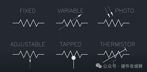
Types of PCB Resistors
There are various types of resistors available to meet different applications. They can be classified based on structure, material composition, size, and other factors.
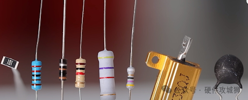
Here are some of the most common types of PCB resistors:
Carbon Resistors
Carbon composition resistors are the oldest type of resistor. They are made from a solid cylindrical rod of ceramic and carbon particles. The main characteristics of carbon resistors include:
-
Low cost, but poor tolerance (±10%) due to temperature effects.
-
Used in applications where precision is not critical.
-
Available in power ratings from 1/4 to 2 watts.
-
Commercial-grade stability.
-
Higher noise compared to other types.
-
Prone to voltage coefficient issues.
Carbon Film Resistors
Carbon film resistors have a thin layer of carbon deposited on a ceramic rod. They exhibit better performance than carbon composition resistors:
-
Improved tolerance (±5%) and stability.
-
Low temperature coefficient.
-
Available in power ratings from 1/8 to 1 watt.
-
Extremely low inductance and capacitance.
-
Low noise operation.
-
Better surge voltage handling.
Metal Film Resistors
For better accuracy and stability, metal film resistors are used. They are made by depositing a thin film of nickel-chromium or tin oxide on a ceramic substrate. The main features of metal film resistors include:
-
Better tolerance (±1%) and temperature stability.
-
Lower noise than carbon composition and carbon film resistors.
-
Power ratings range from 1/10 watt to 1 watt.
-
Capable of handling higher peak voltages.
-
Low voltage coefficient and good stability.
Metal Oxide Film Resistors
Metal oxide film resistors use metal oxide materials like tin oxide instead of metal films. This provides further improvements:
-
Excellent tolerance as low as ±0.5%.
-
Extremely stable over time and temperature variations.
-
Low thermoelectric voltage, reducing noise.
-
High-frequency capability up to GHz range.
-
High reliability and pulse handling capability.
-
Used in high-precision testing equipment.
Wirewound Resistors
Wirewound resistors achieve resistance by winding resistance wire around a ceramic core. Key features include:
-
High power handling capability, up to 100 watts or more.
-
Can achieve low resistance values.
-
Inductive, not suitable for high-frequency use.
-
Commercial tolerance of about ±5%.
-
Typically encapsulated in aluminum or ceramic housings.
-
Prone to thermoelectric effects under shock/vibration.
Foil Resistors
Foil resistors are used for low resistance values below 1 ohm. They consist of metal alloy foils bonded to a ceramic substrate.
Features include:
-
Resistance values as low as milliohms.
-
High precision with ±0.005% tolerance.
-
Low TCR, excellent stability.
-
High current capacity.
-
Fully welded structure, no winding.
-
Commonly used in aerospace applications.
Ceramic Resistors
Ceramic composition resistors are made from a layer of ruthenium oxide glaze fused to a ceramic body. They provide outstanding performance:
-
Extremely tight tolerances as low as ±0.02%.
-
Ultra-low temperature coefficient.
-
High stability over time and environmental stress.
-
Withstand repeated thermal shocks without drifting.
-
Used in high-reliability aerospace and military applications.
Fuse Resistors
Fuse power resistors contain a built-in fuse wire that burns out when the current is too high. Under normal conditions, they behave like any other fixed resistor. The main characteristics of fuse resistors include:
-
Provide overload protection for circuits.
-
Power ratings from 1 to 5 watts.
-
The fuse safely disconnects before the main resistor overheats.
-
Can be manually reset by replacing the fuse.
-
Commonly used in power supplies and distribution circuits.
Trimming Resistors
Trimming resistors have adjustable resistance values obtained mechanically (via screws or sliding contacts). This allows for “fine-tuning” the resistance during circuit calibration and testing.
Characteristics of trimming resistors:
-
Variable within a limited range, typically 20-30%.
-
Set to precise values using a screwdriver or small adjustment tool.
-
Sealed structure to prevent environmental contamination.
-
Available in through-hole and SMD packages.
-
Widely used for fine-tuning in analog or precision circuits.
Thermistors
Thermistors are resistors made from semiconductor materials with significant resistance temperature coefficients. This means their resistance value changes significantly with temperature variations.
Thermistor characteristics:
-
Used for temperature measurement, compensation, and control.
-
NTC type resistance decreases with increasing temperature.
-
PTC type resistance increases with increasing temperature.
-
Response times range from seconds to minutes.
-
The relationship between resistance and temperature is highly nonlinear.
Varistors
Varistors are voltage-dependent resistors made from specially formulated metal oxide materials.
Their primary function is transient voltage suppression:
-
Resistance drops sharply with applied voltage.
-
Absorb and limit transient voltage spikes during ESD or surges.
-
Used to protect sensitive electronic devices from damage.
-
Bidirectional operation for AC or DC circuits.
-
Energy handling capability specified by joule ratings.
-
Response times in nanoseconds.
Photoresistors
Photoresistors, also known as light-dependent resistors (LDRs), decrease their resistance when exposed to light. They are made from semiconductor materials like cadmium sulfide or cadmium selenide. Key features include:
-
Resistance can change several orders of magnitude under dark and illuminated conditions.
-
Excellent sensitivity to visible light and infrared wavelengths.
-
Used in electronic products that utilize light sensing and activation.
-
Slow response time makes them unsuitable for fast light signals.
-
Packaging must allow light to reach the photosensitive area.
Magnetoresistors
Magnetoresistors are made from materials whose resistance changes with magnetic fields. Some types include:
-
Giant magnetoresistors using nickel-iron films.
-
Gallium arsenide semiconductor.
-
Giant magnetoresistive multilayer devices.
-
Tunnel magnetoresistors utilizing magnetic tunnel junctions.
Useful characteristics of magnetoresistors include:
-
Detecting magnetic field strength and direction.
-
Providing electrical isolation from sensing media.
-
Rugged and capable of operating over a wide temperature range.
-
Used in magnetic field sensors, current sensors, and isolators.
-
Exhibit high sensitivity to small magnetic changes.
Surface Mount Resistors
Surface mount device (SMD) resistors are designed for surface-mounted PCB components rather than through-hole mounting. They are much smaller and allow for very high component density on the circuit board.
Some characteristics of SMD resistors include:
-
Rectangular, square, or oval ceramic bodies with terminals on the bottom.
-
Terminals are thick film, solder-coated nickel strips.
-
Marked with numerical resistance codes instead of color bands.
-
Resistance range typically from 10 ohms to 22 Mohms.
-
Power ratings from 0.05 watts to 1 watt.
-
Tolerances as low as ±0.1%.
-
Sizes specified in imperial (01005) or metric (0402) codes.
The small size of SMD resistors enables more components to be mounted on increasingly smaller PCBs. Automation assembly and cost savings are additional advantages compared to through-hole resistors.
Resistor Marking Codes
Due to their small size, resistors must use color bands, alphanumeric codes, or other markings directly printed on the resistor body to indicate their resistance value and tolerance.
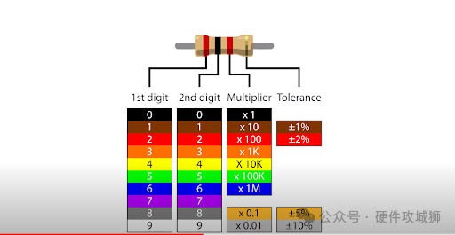
Color Bands
The color band system has been used to represent resistance values since the 1920s.
-
Three-band resistors have two significant digit color bands and a third multiplier band.
-
Four-band resistors add a fourth tolerance color band for higher accuracy.
-
Five-band and six-band resistors also exist to meet high stability requirements.
SMD Marking Codes
Due to their smaller size, SMD resistors use compact numerical resistance and multiplier codes instead of color bands.
Some typical schemes include:
-
Three-digit code – The first two digits represent resistance, and the third digit represents the multiplier.
-
Four-digit code – The first three digits are resistance, and the fourth digit is the multiplier.
-
EIA-96 system – Two-digit resistance with a letter indicating the multiplier.
Thus, 472 equals 47 x 100 = 4.7KΩ. 15R2 = 15 x 0.01 = 150 ohms.
Laser trimming of resistor layers is also used to achieve very tight tolerances for SMD resistor values.
How to Choose the Right Resistor
Selecting the appropriate resistor for a specific PCB application requires consideration of several important factors:
Resistance Value
The optimal resistance depends on the circuit design requirements and is calculated using Ohm’s Law. Standard EIA decade values are typically chosen.
Tolerance
Tolerance indicates the accuracy of the resistor’s nominal value. ±1% or better tolerances are used for precision circuits. For non-critical applications, larger tolerances of about ±5% or ±10% can be acceptable to reduce costs.
Power Rating
The power rating must exceed the maximum expected power dissipation of the resistor. The power rating depends on physical size. 1/4 watt (or 250mW) can handle most low-power circuits. Power supplies or heaters may require higher wattages.
Temperature Coefficient
The inherent change in resistance per degree of temperature variation. A lower coefficient provides better stability in precision circuits. The maximum operating temperature must also be considered.
Rated Voltage
The rated voltage must exceed the maximum voltage drop across the resistor, with a safety margin. Power and other high-voltage applications require higher rated voltages.
Size
The physical size can determine SMD versus through-hole form factors. Height restrictions may apply to dense boards. High-power resistors are larger than low-power resistors.
Noise
Low-noise film resistors should be used in high-gain analog circuits and RF/data transmission lines. Wirewound coils have some inductance and can generate noise.
Response Time
Select resistors with appropriate transient response for timing circuits, pulse operations, and high-frequency applications.
By considering these factors, the best type and specifications of PCB resistors can be selected.
Applications of PCB Resistors
Resistors are ubiquitous in various printed circuit board applications, including:
Voltage Dividers
Two or more resistors connected in series across a voltage source form a simple yet useful voltage divider circuit. This generates a lower voltage tap from a higher supply voltage.
Voltage dividers are used in power supplies, bias networks for transistor amplifiers, ADC interfaces, and many other applications requiring a small portion of a voltage rail. Careful selection of appropriate resistance values can achieve the desired voltage division ratio.
Current Limiting
Connecting resistors in series with LEDs, integrated circuits, and other sensitive electronic components can limit the current flowing through them. The resistance value is calculated to reduce excess voltage to the level required by the device. This can prevent damage from surge currents, overloads, or short circuits.
Pull-Up/Pull-Down
Pull-up and pull-down resistors connect between integrated circuit logic outputs and positive or negative power rails (ground). When the IC output is high, it ensures a known logic voltage level.
Pull-up/pull-down resistors provide defined default conditions to prevent logic errors and false triggering. They are critical for the reliable operation of all digital logic families.
Bias Networks
Providing appropriate DC bias voltage or current levels through resistors allows analog integrated circuits like transistor amplifiers and operational amplifiers to operate in their linear regions. Biasing resistors help stabilize these active devices under optimal static conditions to meet circuit design requirements.
Feedback Circuits
Resistors are essential components in the feedback loops of operational amplifiers, ADCs, DACs, and other analog circuits. They control gain, frequency response, stability, and output impedance based on the intended function.
Timing Circuits
Combining resistors with capacitors forms RC timing circuits that generate known time constants. They are used in oscillators, timers, pulse generators, and other circuits requiring delays, waveform shaping, or frequency control.
Termination
Resistors are commonly used for terminating transmission lines and wiring for RF, video, digital data, USB, etc. Termination resistors match the line impedance to minimize signal reflections. This allows maximum power transfer to improve signal integrity.
Surge Protection
Varistors and fuse resistors help protect sensitive semiconductor devices from high-voltage transients. They clamp or absorb dangerous voltage spikes to prevent damage to ICs, chips, and other components. Resistors also help limit current during electrostatic discharge (ESD) events.
Temperature Compensation
Thermistors measure temperature changes and adjust their resistance accordingly to compensate for variations in other components caused by thermal effects. This maintains circuit stability and performance.
Voltage Regulation
Resistors used in conjunction with Zener diodes, transistors, and other active components help build stable DC voltage regulator circuits. These resistors can achieve adjustable output voltages, limit current, and dissipate excess power from the supply.
Filtering
Resistors combined with capacitors form low-pass, high-pass, band-pass, and band-stop analog filters. They filter out unwanted signals and pass frequencies of interest. Filtering helps eliminate noise, harmonics, and interference.
Bleeders
High-resistance power resistors slowly discharge capacitors after the device is powered off. Bleeder resistors can safely dissipate stored energy to prevent electric shock hazards. They are common in power supplies, defibrillators, and industrial electronics.
Split Networks
Series and parallel resistor ladder networks provide multiple precise voltage taps from a single reference. They create resistor voltage dividers for A/D converters, calibration, voltage scaling, and other applications.
By leveraging the various roles resistors can play, PCB designers utilize them to build robust, reliable, and efficient electronic circuits.
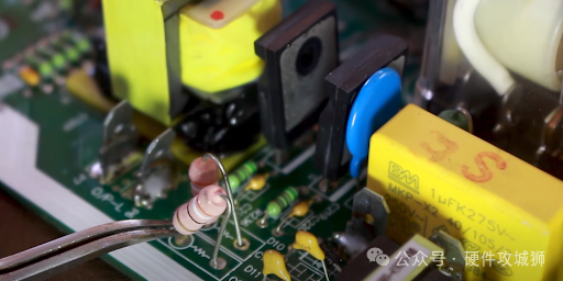
PCB Resistor Soldering
Leaded resistors are inserted through PCB holes and soldered in place. This securely holds the components and establishes strong electrical connections. Some tips for manually soldering resistors on the board include:
-
Use the appropriate soldering iron temperature (for leaded components, 650-700°F).
-
Apply flux to the component leads and PCB pads to aid wetting.
-
Ensure resistor leads are fully inserted into the PCB holes before soldering.
-
Heat both the resistor and the pad.
Automated Pick-and-Place Assembly
High-volume PCB manufacturing employs dedicated pick-and-place machines suitable for SMD components. It automates the assembly process, achieving incredible speed, precision, and reliability.
Some features include:
-
High-speed vacuum nozzles pick components from feeders or tape.
-
The machine places thousands of parts per hour with an accuracy of up to 0.01 mm.
-
Optical devices align components and verify part presence.
-
Eliminates human errors and placement variations.
-
Reduces manufacturing defects compared to manual assembly.
-
Custom nozzles, feeders, and tape sizes for any component package.
-
The software integrates with CAD datasets to generate programs.
-
Reduces overall assembly costs and shortens time to market.
Advanced pick-and-place systems enable extremely dense component loading on compact PCBs.
Embedded Thin Film Resistors
Due to parasitic inductance and capacitance issues, discrete resistors are unsuitable for special applications like RF and microwave boards. Instead, embedded thin film resistors can be directly laser-trimmed onto inner layers of the board.
Benefits include:
-
Resistance tolerances as low as ±1%.
-
Excellent high-frequency characteristics exceeding GHz range.
-
Stable resistance under temperature fluctuations.
-
Thin profile does not occupy vertical space on the board.
-
Compatible with standard PCB laminates like FR-4.
-
Suitable for digital and high-speed analog signals.
-
Improves signal integrity by eliminating discrete components.
-
Reduces assembly costs by integrating passive components into the PCB.
Embedded resistors continue to advance PCB miniaturization and performance, especially to meet high-frequency demands.
PCB Resistor Testing
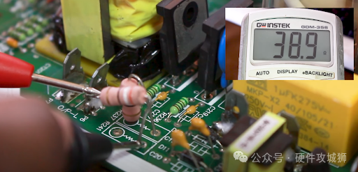
Verifying the correctness of resistors on assembled boards is crucial for reliability. Some important testing methods include:
-
Online testing checks resistors installed on the circuit board.
-
Continuity testing confirms connections and detects open circuits.
-
Voltage measurements across resistors can verify correct voltage drops.
-
Automated optical inspection looks for visible defects and anomalies.
-
X-ray inspection can reveal hidden issues like cracks or voids.
-
Stress testing under temperature cycling, vibration, and power cycling qualifications.
-
Applying ESD shocks to check robustness and surge handling capability.
Thorough testing of resistors at both the bare board and assembled board stages can identify faults before shipment. This can prevent premature field failures.
PCB Resistor Failure Modes
Although resistors are simple components, they can still fail due to overstress, contamination, wear, or design flaws. Some standard failure modes to be aware of include:
-
Excessive power leading to overheating.
-
Open circuits due to lead breakage or internal fuse burnout.
-
Resistance value changes due to thermal or mechanical stress.
-
Intermittent failures due to cracking of the resistor body or component.
-
Short circuits or arcing caused by conductive debris.
-
Soldering damage, such as pad lifting or thermal shock.
-
Parameter changes over time and environmental exposure.
-
Open circuits caused by mechanical shock/vibration.
-
Resistance increase due to peeling of resistor film materials.
-
Resistor power ratings insufficient to meet application demands.
Understanding how resistors fail and considering reliability risks during design can reduce potential field failures.
Conclusion
Resistors are essential components that enable nearly every electronic printed circuit board to function properly by controlling current and voltage drops. From high-precision applications to basic pull-up needs, resistors provide support for PCBs through their versatility, low cost, and reliability.
Electrical engineers can maximize the use of these fundamental passive devices to build high-performance, durable circuit boards and systems by using the provided guidelines to select the appropriate resistor types, sizes, and characteristics. With ongoing advancements in materials and manufacturing, resistors will continue to be a cornerstone of electronic design in the future.
— End —
Disclaimer: This account maintains neutrality regarding all original and reprinted articles’ statements and viewpoints. The articles are provided for readers’ learning and communication purposes. Copyright for articles, images, etc., belongs to the original authors. If there is any infringement, please contact for removal.-Recommended Reading-
Shocking! An 8-year resume of an electronic engineer graduate from Fudan University!
Why do many MCU companies imitate STM32?
Support quality content by “sharing, liking, and viewing” 👇