In the previous article, we introduced the basic knowledge and core concepts of the CANopen protocol. In this article, we will continue to explain the fundamentals of CANopen communication. This series mainly covers the basic content of the CANopen protocol, including the object dictionary, services, SDO, PDO, and master/slave nodes. For CANopen software and hardware solutions or training services, please contact the Hongke Industrial Control team at 400-999-3848 or [email protected]!
Previous Review: Hongke Insights | The Simplest and Most Practical Introduction to CANopen, After Reading This You Will Understand (1)
1
CANopen Frame
CANopen frame
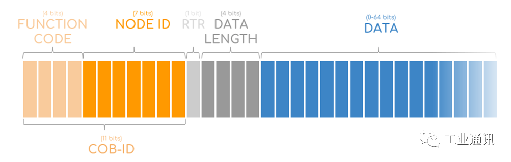
To understand CANopen communication, it is necessary to break down the CAN message of CANopen. As shown in the figure below, the 11-bit CAN ID is called the Communication Object Identifier (COB-ID), which is divided into two parts. The first 4 bits correspond to the function code, and the next 7 bits contain the node ID.
To understand how the COB-ID works, we need to start with the predefined allocation of identifiers in a simple CANopen network.
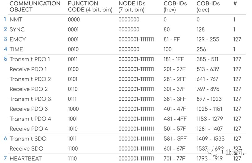
As shown in the figure above, the COB-ID (381, 581, etc.) is associated with communication services (such as transmitting PDO 3, transmitting SDO, etc.), thus detailing which node is sending/receiving data and what service is being used. For example, a CANopen device with a node ID of 5 will transmit SDO using the 11-bit CAN ID 585, corresponding to the binary function code 1011 and node ID 5 (binary 0000101).
2
CANopen Communication Protocol/Service
CANopen communication protocols/services
Next, we will briefly introduce the 7 types of services in CANopen and how they utilize the 8 data bytes of the CAN frame.
1. Network Management (NMT)
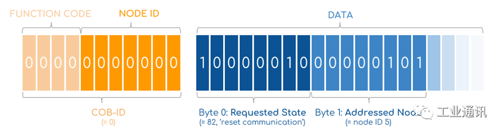
Possible commands include switching to operational (state 01), stopped (state 02), pre-operational (state 80), reset application (81), and reset communication (82).
For example: Set node 0x06 to operational mode: 000 01 06
2. Synchronization (SYNC)
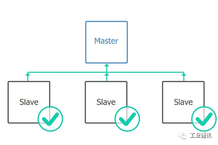
The SYNC message is used to synchronize the inputs and responses of several CANopen devices—typically triggered by the application master. The application host sends a SYNC message (COB-ID 080) to the CANopen network (with or without a SYNC counter). Multiple slave nodes can be configured to respond to SYNC and can respond by transmitting simultaneously captured input data or by setting outputs simultaneously with nodes participating in the synchronization operation. Using a SYNC counter allows configuration of several sets of synchronized devices.
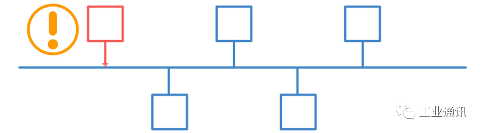
3. Emergency (EMCY)
The emergency service is used when a device encounters a fatal error (e.g., sensor failure) and allows it to indicate this to the rest of the network. The affected node sends a single EMCY message (e.g., COB-ID 085 for node 5) to the network with high priority. The data byte contains information about the error, which can be looked up for details.
4. Timestamp (TIME) [PDO]
This communication service allows the assignment of global network time. The time service contains 6 bytes of date and time information. The application host sends a TIME message with CAN ID 100, where the first 4 data bytes contain the time in milliseconds after midnight, and the next 2 bytes contain the number of days since January 1, 1984.
5. Process Data Object [PDO]
The PDO service is used to transmit real-time data between devices, such as measurement data like position or command data like torque requests. In this regard, it is similar to broadcast data parameters in J1939. We will provide a detailed introduction to the PDO service in the next article.
6. Service Data Object [SDO]
The SDO service is used to access/change values in the object dictionary of CANopen devices. For example, when the application master needs to change certain configurations of a CANopen device, it can achieve this through the SDO service. We will provide a detailed introduction to the SDO service in the next article.
7. Node Monitoring (Heartbeat) [SDO]
The heartbeat service has two purposes: to provide an “active” message and to confirm NMT commands. NMT slaves periodically send heartbeat messages (e.g., node 5 with CAN ID 705) that contain the node’s “status” in the first data byte. If no messages are received within a specific time limit, the “consumer” of the heartbeat message (e.g., the NMT master and any other optional devices) will respond.
For example: Node 5 in pre-operational mode periodically sends: 705 7F
In the next article, we will continue to explain the relevant knowledge of CANopen communication, including the object dictionary, SDO, PDO, etc. Please follow our public account to get updated content first. Hongke has been deeply involved in the fields of CAN, CANopen, etc., for many years, with strong technical strength. We have launched CANopen development source code, CANopen data loggers, and products supporting CANopen protocols such as gateways, boards, and IO for the domestic market. In addition, to meet customer training needs in CANopen, Hongke has also launched related course training services. Please call 400-999-3848 to learn more about Hongke.
▎Previous Reviews