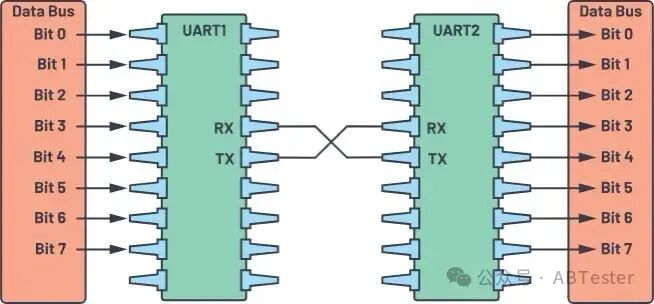
UART (Universal Asynchronous Receiver/Transmitter) is the most common and simplest communication method in the embedded world. Its core idea is: parallel data input → serialized bit stream by frame → the receiver samples and recovers at the same baud rate. It is simple to implement and low in cost, but has limited scalability. This article will guide you from basic concepts to engineering practices, providing a systematic understanding of UART.
1. What is UART? Why has it not been eliminated?
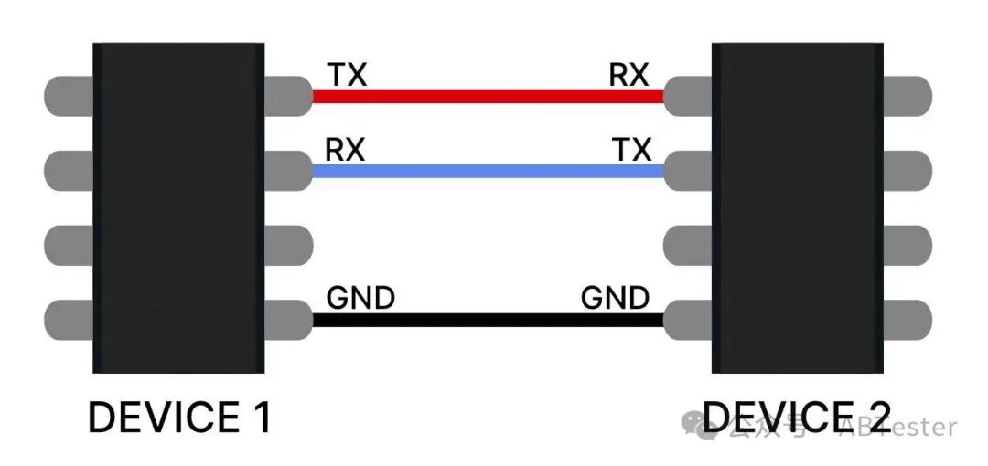
UART is not a “bus standard” but an asynchronous point-to-point communication protocol. Its typical features are:
- It only requires two wires: TX (transmit), RX (receive), plus a common ground line GND.
- Asynchronous: there is no additional clock line, and both parties rely on consistent baud rates to ensure correct sampling.
- Point-to-point: by default, it can only communicate one-to-one, unlike I²C/SPI which can connect multiple devices.
Why has it not been eliminated?
- Extremely low cost (hardware is almost free).
- Simple configuration (baud rate + data bits/parity/stop bits).
- It remains a necessity in embedded debugging, log output, firmware downloading, and testing tools.
2. Composition of a UART Data Frame

What does a data frame look like? This is the core of UART.
- Start Bit
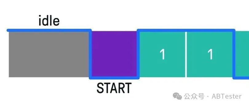
- In idle state, the line remains high.
- The start bit pulls the line low, indicating “I am about to send data”.
- Data Bits

- 5–9 bits, most commonly 8 bits (1 byte).
- The least significant bit (LSB) is sent first, which is different from most protocols.
- Parity Bit (optional)
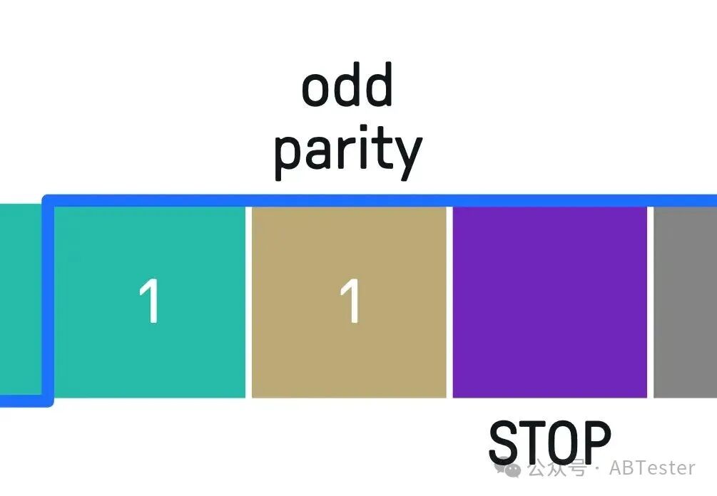
- Odd/even parity is used to detect single-bit flips.
- It cannot guarantee absolute reliability; it is just a lightweight detection method.
- Stop Bits
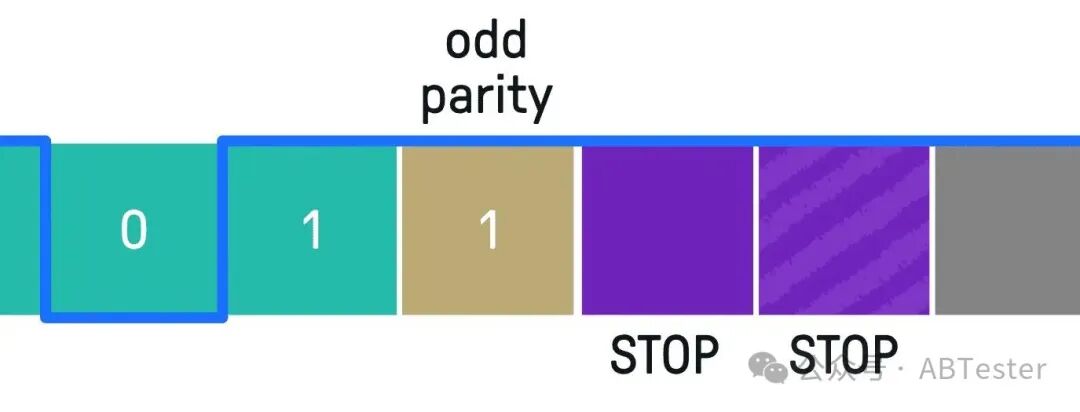
- 1–2 bits high level.
- The purpose is to “leave some breathing room” for the receiver to complete sampling.
👉 A common configuration is called 8N1: 8 data bits, N (no parity), 1 stop bit.
3. Baud Rate and the “Cost of Asynchronous”
UART is asynchronous, so matching baud rates is crucial.
- Common baud rates: 9600, 19200, 115200 …
- Tolerance: an error exceeding ~10% will generally cause loss of synchronization.
- Limited by line length and electromagnetic interference, higher baud rates are more prone to errors.
Engineering experience:
- MCU internal register configurations must strictly follow the manual formulas (involving peripheral clocks, dividers, oversampling).
- It is recommended to use a logic analyzer during the debugging phase to capture a frame and check if the start bit, data bits, and stop bits are of equal width.
4. Advantages and Disadvantages of UART
Advantages
- Widespread hardware availability, cost is almost zero.
- Point-to-point is simple and intuitive.
- Only requires two wires, making wiring easy.
- No need for a synchronized clock, simplifying wiring.
Disadvantages
- Only point-to-point, does not support multi-master and multi-slave.
- Limited bandwidth, usually ≤1.5 Mbps.
- No built-in frame synchronization or retransmission mechanism.
- Suitable for communication within 15 meters; for longer distances, physical layers like RS-232/RS-485 are needed.
5. How does UART hardware work internally?
UART is essentially a “serial-parallel converter”.
- Transmitter (TX)
- Reads a byte in parallel from the data bus.
- Adds start bit, parity bit, and stop bit at the front and back.
- Serially transmits according to the baud rate timing.
- Receiver (RX)
- Detects the start bit going low and begins sampling at the baud rate.
- Collects data bit by bit and verifies the parity bit.
- Removes frame control bits and finally outputs to the local data bus in parallel.
In summary: parallel in, serial out; serial in, parallel out.
6. Why is there a need to “encapsulate another layer of protocol” in engineering?
UART only solves “bit-level transmission” but does not manage “data packets”. In real projects, if bytes are sent directly without encapsulation, problems can easily arise:
- Data loss → the receiver does not know how many bytes were lost.
- Noise interference → if a byte is corrupted, it may cause the entire data stream to become misaligned.
- Unable to distinguish the boundaries of “commands/data/parity”.
Therefore, a custom protocol is usually encapsulated on top of UART: Header(2B) | CMD | LEN | DATA… | CRC | Tail(2B)
- Frame header/footer: used for packet alignment.
- CMD/LEN: clearly defines command type and data length.
- CRC: ensures data integrity.
This way, issues like frame loss and frame errors can be handled at the application layer, improving robustness.
7. Typical Application Scenarios
- Embedded development debugging: the most common “printf serial port”.
- Production line testing/upgrading: test equipment uses UART to download firmware to the MCU.
- Low-speed device communication: such as GPS modules, Bluetooth modules, sensors.
- Legacy systems: the RS-232 interface of old PCs is a typical implementation of UART.
8. Practical Advice for Beginners
- For beginners, using the 9600-8N1 configuration is the most stable.
- During development, use a logic analyzer to observe and avoid “blind matching”.
- Do not neglect GND! Many beginners experience communication issues due to not connecting ground.
- If running a protocol stack (like Modbus RTU), be sure to add a state machine and CRC on top of UART.
- When writing driver code, make the baud rate calculation a function to avoid hardcoding.
Conclusion
UART is like the “Hello World” of the embedded world. Its structure is extremely simple, yet it can cover a wide range of scenarios including debugging, testing, downloading, and data exchange. Understanding its frame structure, asynchronous sampling mechanism, and fault-tolerant protocol design will not only help you write your first piece of embedded code but also help you avoid common “serial port pitfalls” in subsequent projects.