Electronic products, such as computers, mice, chargers, and even cars, have many interfaces around us. This article will introduce you to these interfaces, showing what they look like, where they are used, how to use them, and what their principles are. This article serves as a simple description for beginners.
-
1. Serial Port
-
2. UART
-
3. TTL Level
-
4. USB
-
5. RS-232
-
6. RS-485
-
7. IIC
-
8. SPI
-
9. CAN
-
10. 1-WIRE
1. Serial Port
1. Overview of Serial Ports
The serial interface, commonly referred to as the serial port, is also known as the COM port. This is a general term for any interface that uses serial communication, and it is a hardware interface.
2. Male and Female Connectors
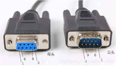
There are male and female connectors; you can remember that the one with holes on the left is the female connector, while the other is the male connector.
3. Serial vs. Parallel
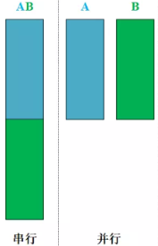
Serial: A communication method where one bit of data is transmitted at a time over a computer bus or other data channel, continuously performing this single process.
Parallel: A communication method that transmits several bits of data simultaneously over a serial port, thus parallel communication is faster than serial communication.
2. UART
UART stands for Universal Asynchronous Receiver/Transmitter, which means a universal asynchronous transceiver. UART includes TTL level serial ports and RS-232 level serial ports, and both devices communicating using UART must comply with the UART protocol.
3. TTL Level
1. Overview of TTL
TTL stands for Transistor-Transistor Logic, a type of level logic, which is transistor-transistor logic.
2. Standard TTL Level Logic
Logic 1 represents a high level, connected to the power supply VCC, while logic 0 represents a low level, connected to ground.
- Logic 1, high level, VCC (3.3V/5V)
- Logic 0, low level, GND (0V)
TTL has a voltage range divided into output high, low levels and input high, low levels; output high level is represented, output low level is represented; input high level is represented, input low level is represented.
For TTL level devices, when the input voltage is above 2V, it will be recognized as logic 1, and when the input low level is below 1.2V, it will be recognized as 0. This is why the output high level is 2.4V, above 2V; and the output low level is 0.8V, below 1.2V. The following is the standard TTL level, with various types of TTL having different voltage ranges.
- ,
- ,
3. USB to TTL
Those who have worked with the 51 microcontroller have used the CH340G module to download HEX files. The purpose of this module is to convert USB to TTL level, as the microcontroller’s levels are generally TTL levels. The internal chip of the module is CH340T, which is officially recommended by ST.
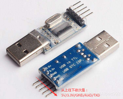
<span>USB to TTL Module</span>Using the CH340T chip, the circuit schematic for USB to TTL level.
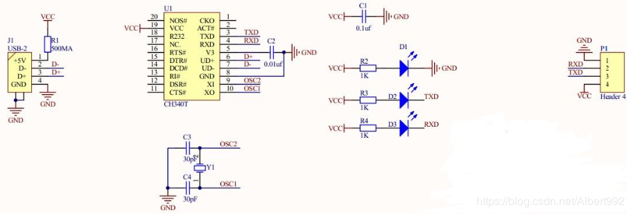
<span>USB</span><span>to</span><span>TTL</span><span>Schematic</span>4. Connection with Microcontroller
Communication between TTL level devices requires only three signal lines: TXD, RXD, and GND. The connection to the microcontroller is straightforward; a 3.3V microcontroller connects to 3.3V, and a 5V microcontroller connects to 5V. If the microcontroller has separate power supply, do not connect 3.3V and 5V.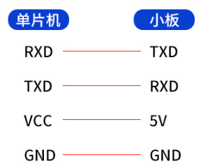
<span>Connection of USB to TTL Module with Microcontroller</span>
4. USB
1. Overview of USB
USB stands for Universal Serial Bus, which is an external bus standard used to specify the connection and communication between computers and external devices. It is an interface technology applied in the PC domain, characterized by fast transmission speeds, support for hot-swapping, and the ability to connect multiple devices.
We can see USB in many places, such as mice, keyboards, and mobile phone chargers. Almost all electronic charging devices now use USB interfaces. Below are the physical interfaces of various USB types.
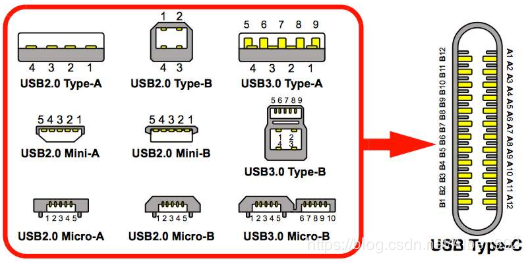
<span>USB</span><span>Interface Classification</span>2. USB Rates
1MB/s=8Mbps (1 Byte equals 8 bits)
USB1.0 Low Speed transmission rate is 1.5Mbps;
USB1.1 Full Speed transmission rate is 12Mbps;
USB2.0 High Speed transmission rate is 480Mbps;
USB3.0 SuperSpeed transmission rate is 5Gbps;
USB3.1 Gen2 SuperSpeed+ transmission rate is 10Gbps;
3. USB Interface Definition
The most common Type-A USB interface is defined as follows.
| Pin# | Name | Color |
|---|---|---|
| 1 | VBUS/+5V | Red |
| 2 | D-/Data-/DM | White |
| 3 | D+/Data+/DP | Green |
| 4 | GND | Black |
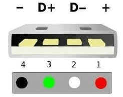
<span>Type-A</span><span>Interface</span>5. RS-232
1. Overview of RS-232
The RS-232 interface complies with the serial data communication interface standards set by the Electronic Industries Alliance (EIA) in the United States. The original full name was EIA-RS-232 (abbreviated as 232, RS232). It is widely used for connecting computer serial interface peripherals, defining connection cables and mechanical, electrical characteristics, signal functions, and transmission processes.
2. RS-232 Level Logic
RS-232 differs from TTL level logic and uses negative logic, where -12V represents a high level logic 1, and +12V represents a low level logic 0, with standard voltage ranges.
- High level, logic 1, -15V to -3V
- Low level, logic 0, +3V to +15V
In addition to TTL and RS232, a common CMOS level standard is also present, with the following voltage ranges:
- ,
- ,
3. DB9 Interface Definition
The following diagram shows the definitions of DB9 male and female connectors, with the most commonly used being RXD, TXD, and GND, the three signals.
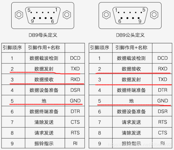
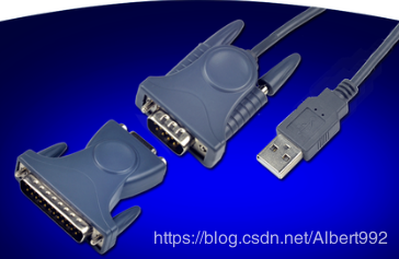
<span>DB9</span><span>Male and Female Connector Signal Definitions</span>In industrial settings, DB-25 RS232 is also used, and DB9 and DB25 interfaces can be converted.
<span>DB9</span><span>to</span><span>DB25</span>4. USB to RS-232
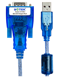
USB to 232 can first convert USB to TTL, and then TTL to RS232. Of course, there are many USB to RS232 cables available on the market, which have integrated conversion circuits. For example, a certain USB to RS232 uses two chips: FT232 and SP213.
<span>USB</span><span>to</span><span>RS232</span><span>Cable</span>5. TTL and RS-232 Conversion
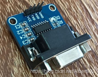
Microcontroller interfaces are generally TTL level. If connecting to RS232 level peripherals, a TTL to RS232 module is needed, with bidirectional conversion.
The most commonly used chips for converting between TTL and RS232 are MAX232 and SP3232.
<span>TTL and RS-232 Conversion Module</span>6. RS-485
1. Overview of RS-485
RS-485, like RS-232, is also a serial communication standard. The current standard name is TIA/EIA-485-A, commonly referred to as RS-485. RS-485 compensates for the short communication distance and low speed of RS-232.
RS-485 differs from RS-232 in that it uses differential transmission, utilizing a pair of twisted wires, one defined as A and the other as B.
2. RS-485 Level Logic
RS-485 uses differential transmission, generally consisting of a transmitter and a transceiver. The following diagram shows a typical functional block diagram of a transceiver.
For the enable signal, the letter with a line above indicates low level effective, while the one without indicates high level effective.
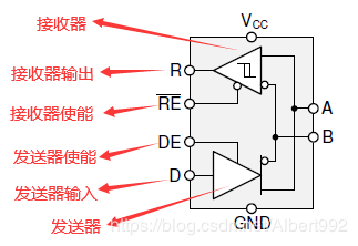
<span> RS-485 Internal Structure</span>
For the transmitter, the following truth table applies:
- When the driver enable pin is high, the differential output follows the logic state at the data input. A high at the input causes A to go high and B to go low. In this case, the defined differential output voltage is positive. When low, the output state reverses, becoming high and low, which is negative.
- When low, both outputs become high impedance. In this case, the logic state at the input is irrelevant.
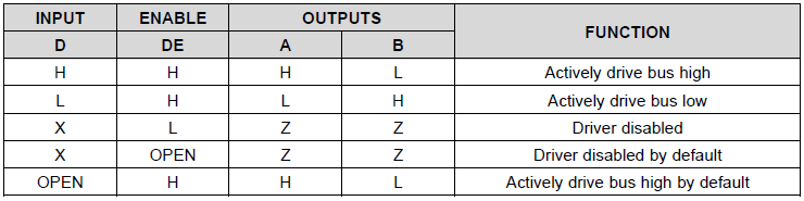
<span>RS-485</span><span>Transmitter Truth Table</span>For the receiver, the following truth table applies:
- When the receiver enable pin is low, the receiver is activated. When the defined differential input voltage is positive and above the positive input threshold, the receiver output goes high. When negative and below the negative input threshold, the receiver output goes low. If between the two, the output is uncertain.
- When high or floating, the receiver output is high impedance, regardless of the magnitude and polarity.
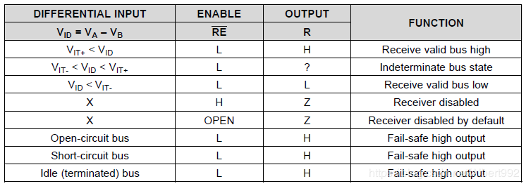
<span>RS-485 Receiver Truth Table</span>RS-485 Level Logic Explanation
Many transceivers meet or exceed the TIA/EIA-485A specification. In practical use, the device’s SPEC parameters take precedence.

3. TTL and RS-485 Conversion
Converting TTL to RS-485 is common, and there are many transceiver chips available on the market, such as MAX485, which is also very easy to use. Generally, the left side connects to the MCU’s GPIO for control.
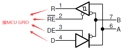
<span>TTL to RS-485</span>4. RS-232 and RS-485 Conversion
Conversion between RS-232 and RS-485 is possible. One method is to convert RS-232 to TTL, and then TTL to RS-485. There are also chips that support direct conversion from RS-232 to RS-485, allowing bidirectional conversion.
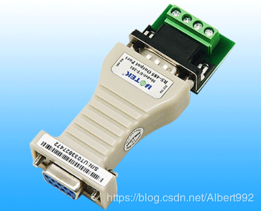
<span>RS-232 and RS-485 Conversion Module</span>7. IIC
1. Overview of IIC
The IIC bus is a simple, bidirectional two-wire synchronous serial bus developed by Philips. IIC requires only two wires for communication: SDA (Serial Data Line) and SCL (Serial Clock Line).
The following diagram shows a typical structure of the I2C bus, which can have a single master with multiple slaves or a single master with a single slave. Any device on the I2C bus can act as a master, generally, the master is the MCU. When there are multiple masters, one is selected through bus arbitration, and the others operate as slaves.
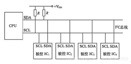
<span>IIC Bus Structure</span>2. IIC Rates
- Standard Mode: 100Kbit/s
- Fast Mode: 400Kbit/s
- High-Speed Mode: 3.4Mbit/s
8. SPI
1. Overview of SPI
SPI stands for Serial Peripheral Interface, which is a high-speed, full-duplex, synchronous communication bus. The speed of SPI is generally higher than that of I2C, typically reaching dozens of Mbps, with different rates for devices acting as masters and slaves.
2. SPI Signal Lines
- MISO – Master Input Slave Output, data input from the master device, data output to the slave device;
- MOSI – Master Output Slave Input, data output from the master device, data input to the slave device;
- SCLK – Serial Clock, clock signal generated by the master device;
- CS – Chip Select, signal enabling the slave device, controlled by the master device;
3. Typical Applications of SPI
The most typical application of SPI is a single master with a single slave. The following diagram shows the wiring method, although it can also accommodate multiple slaves.
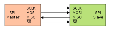
<span>SPI Single Master Single Slave Connection Method</span>9. CAN
1. Overview of CAN
CAN stands for Controller Area Network, a serial communication network that effectively supports distributed control or real-time control. It is now the standard protocol for automotive networks.
2. CAN Level Logic
| Level | Logic | Bus Value |
|---|---|---|
| Dominant Level | 0 | CAN_H=3.5V, CAN_L=1.5V |
| Recessive Level | 1 | CAN_H=2.5V, CAN_L=2.5V |
10. 1-WIRE
1. Overview of 1-WIRE
1-WIRE is a peripheral serial expansion bus technology introduced by the American company DALLAS. Unlike SPI and I2C serial data communication methods, it uses a single signal line to transmit both clock and data, and the data transmission is bidirectional.
2. Typical Block Diagram of 1-WIRE
The following is a typical block diagram of 1-WIRE, showing that there is only one line between the microprocessor and the 1-WIRE device.
When the MCU sends logic 1, through an inverter, the bus presents logic 0, and logic 0 through the inverter of the 1-WIRE device will receive logic 1;
When the MCU sends logic 0, through the inverter, the bus presents logic 1, and logic 1 through the inverter of the 1-WIRE device will receive logic 0;
Similarly, when the 1-WIRE device sends logic 1, the NMOS at Tx will conduct, presenting logic 0 on the bus, which the MCU will receive as logic 1 through the Rx inverter;
When sending logic 0, the NMOS is off, presenting logic 1 on the bus, which the MCU will receive as logic 0;
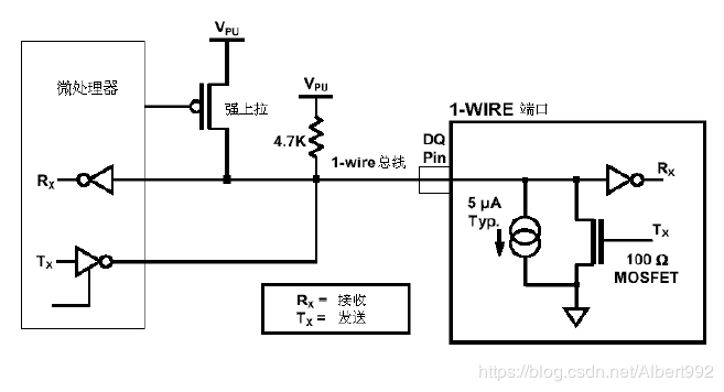
<span>1-WIRE</span><span>Structure Diagram</span>Join the Chip Language Column, we sincerely invite you to join 👇