Some friends asked: Why can’t we go online without configuring an IP address? What is the IP protocol?
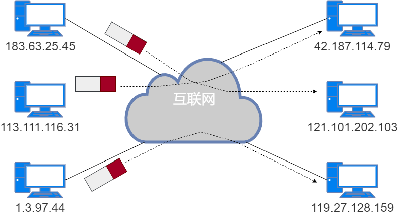
This starts with the TCP/IP protocol; the Internet uses the TCP/IP protocol, among which the IP protocol is one of the most important protocols. The IP protocol sends data packets to the destination host based on the IP address, allowing any two hosts on the Internet to communicate.
The IP protocol is located at the third layer of the OSI reference model, which is the network layer.
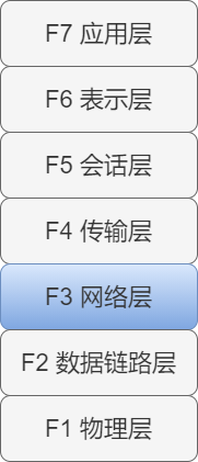
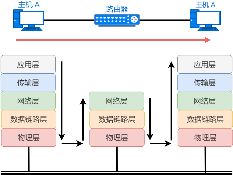
The main function of the network layer is to achieve communication between terminal nodes. This communication between terminal nodes is also called point-to-point communication.
-
Host: A device configured with an IP address, without routing control.
-
Router: A device that has both an IP address and routing control functions.
-
Node: A general term for hosts and routers.
How is data transmitted to the destination?
The data link layer achieves data transmission between two directly connected devices, while the network layer’s IP protocol implements data transmission between two networks that are not directly connected.
For example, in travel, Xiao Mei plans to travel to a distant place, first planning the high-speed train, subway, and bus she will take, and purchasing the corresponding tickets, then formulating a detailed itinerary to record the travel time.
The high-speed train ticket and subway ticket can only move within a certain section, just like data on a network. The starting point is like the source MAC address, while the destination is like the destination MAC address; the entire itinerary acts like the network layer, with the starting point as the source IP address and the destination as the destination IP address.
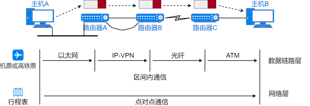
If Xiao Mei only has the itinerary but no tickets, she cannot take the transportation to reach her destination. Conversely, if she only has tickets but doesn’t know which vehicle to take or where to transfer, she probably won’t reach her destination either. Only with both a ticket for a certain section and an overall travel itinerary can she ensure she reaches her destination. Similarly, the network needs the data link layer and network layer to work together to achieve communication with the final destination address.
Basic Knowledge of IP Address
In TCP/IP communication, IP addresses are used to identify hosts and routers. An IP address is a logical address that needs to be manually configured or automatically obtained. To ensure normal communication, each device must configure an IP address.
Definition of IP Address
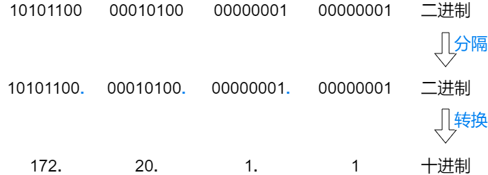
An IP address consists of a 32-bit binary number. For convenience, the 32-bit IP address is divided into 4 groups, with each group containing 8 bits, separated by a “.”, and then each group is converted to a decimal number.
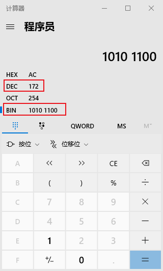
How to quickly convert between binary and decimal?
Using the calculator built into Windows, select the programmer mode to achieve quick conversion between binary and decimal. The default is decimal (“DEC”) input; click “BIN” to switch to binary input. It synchronously displays the values in hexadecimal, decimal, octal, and binary.
How many IP addresses are there?
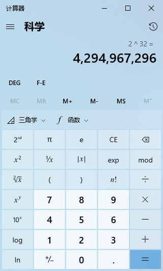
Calculating the 32-bit binary of the IP address gives approximately 4.3 billion IP addresses.

Using the built-in calculator in Windows, select scientific mode to quickly perform exponentiation calculations.
In fact, the development of the network is beyond imagination; the number of devices on the Internet far exceeds 4.3 billion. By November 25, 2019, the global IPv4 addresses were completely exhausted, but even now, people are still using IPv4 and have not been unable to go online because of the lack of addresses. This is because, in addition to IPv6, we use NAT technology to alleviate the problem of insufficient addresses. All the IPs mentioned in this article refer to IPv4, not IPv6.
Composition of IP Address
An IP address consists of a network number (subnet address) and a host number (host address).
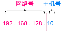
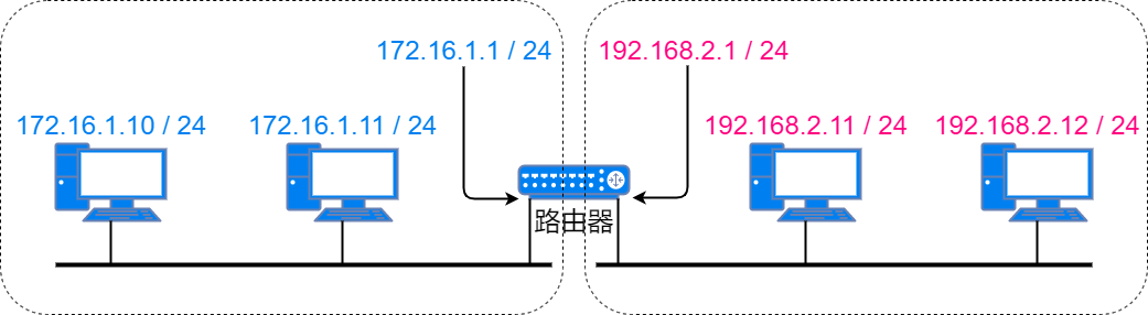
The network number is an identifier for the area where the device is located; devices with the same network number are in the same subnet, while devices with different network numbers communicate through routers. The host number is an identifier for different devices in the same subnet, and duplicate host numbers are not allowed within the same subnet.
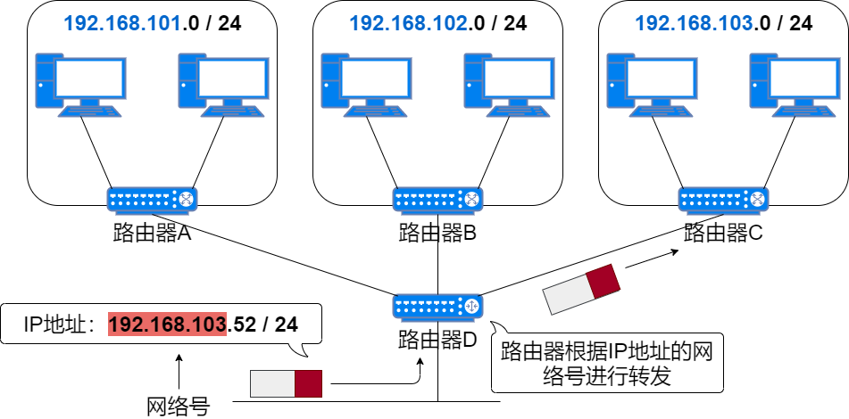
Routers route based on the network number of the destination IP address.
So which bits of the IP address are the network number and which bits are the host number? In the early days, they were distinguished by classful addressing, but now they are distinguished by subnet mask.
Classification of IP Addresses
IP addresses are divided into four classes: Class A, Class B, Class C, and Class D (there is also a reserved Class E).
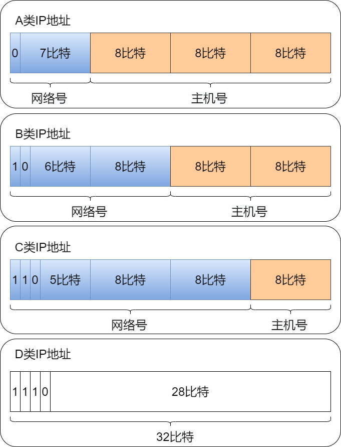
Class A Address
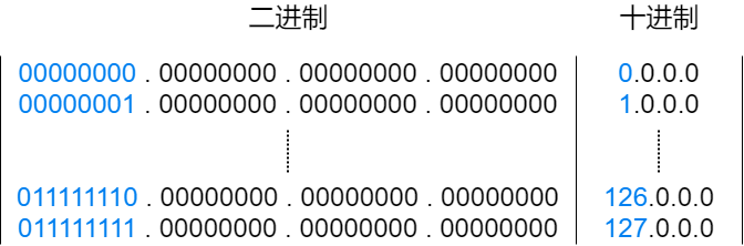
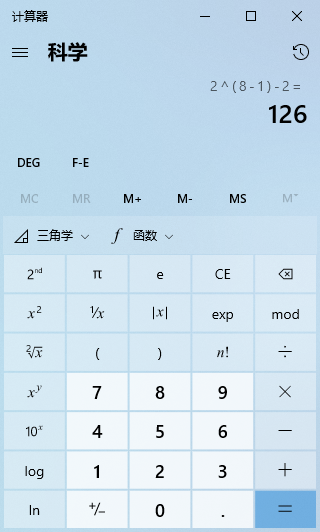
A Class IP address starts with a “0”. From the 1st to the 8th bit is its network number, with the network number range being 0 ~ 127. Among them, 0 and 127 are reserved addresses, so there are 126 usable Class A addresses.
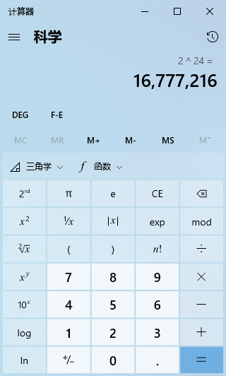
The last 24 bits are the host number, and the number of host addresses for a Class A address is 2 raised to the 24th power, which is 16,777,216 host addresses.

Class B Address
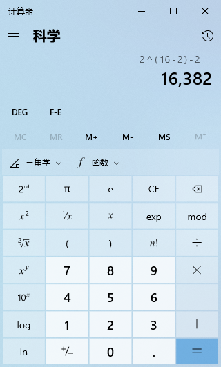
A Class B IP address starts with the first two bits as “10”. From the 1st to the 16th bit is its network number, with the network number range being 128.0 ~ 191.255. Among them, 128.0 and 191.255 are reserved addresses, so there are 16,382 usable Class B addresses.
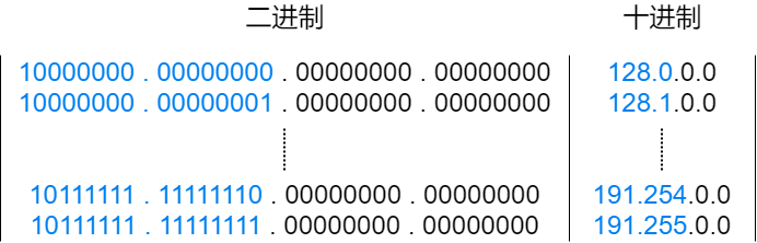
The last 16 bits are the host number, and the number of host addresses for a Class B address is 2 raised to the 16th power, which is 65,536 host addresses.

Class C Address
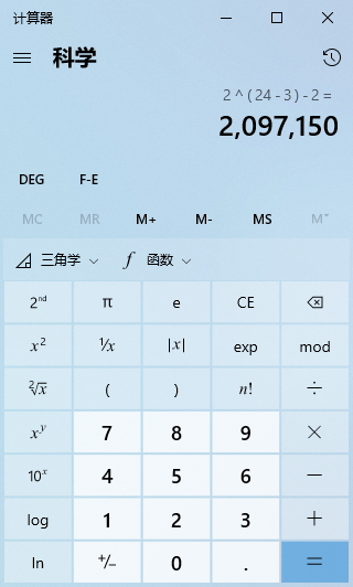
A Class C IP address starts with the first three bits as “110”. From the 1st to the 24th bit is its network number, with the network number range being 192.0.0 ~ 223.255.255. Among them, 192.0.0 and 223.255.255 are reserved addresses, so there are 2,097,150 usable Class C addresses.
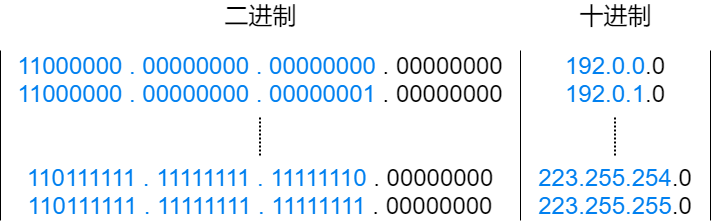
The last 8 bits are the host number, and the number of host addresses for a Class C address is 2 raised to the 8th power, which is 256 host addresses.

Class D Address
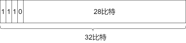
A Class D IP address starts with the first four bits as “1110”. From the 1st to the 32nd bit is its network number, with the network number range being 224.0.0.0 ~ 239.255.255.255. Class D addresses do not have a host number and are used for multicasting.
Subnet Address and Broadcast Address
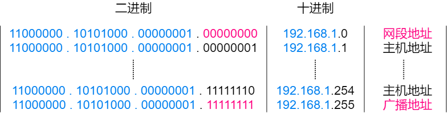
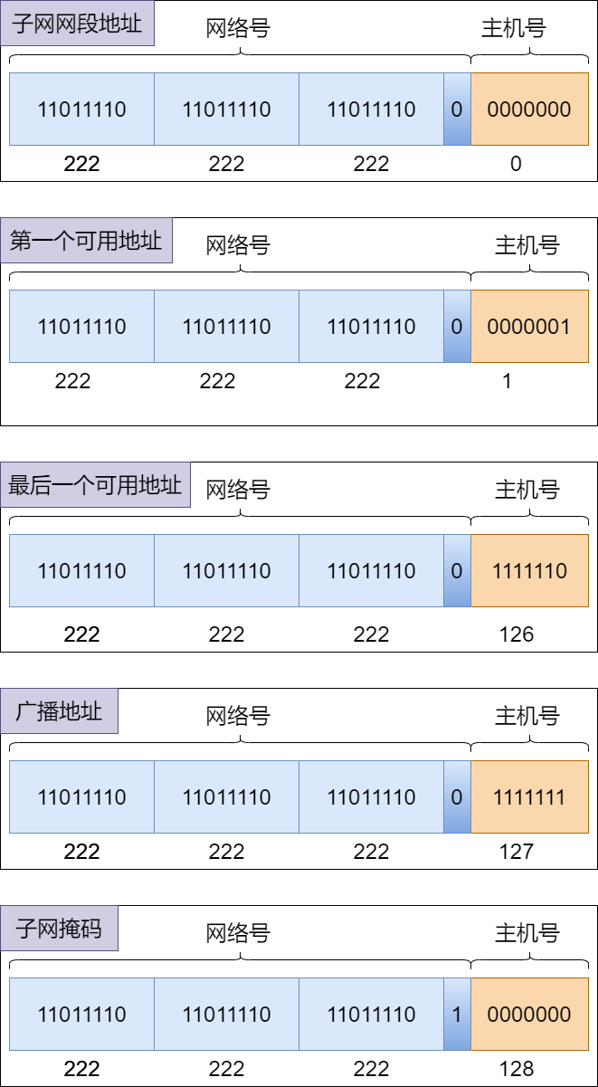
When the host number is all 0s, it indicates a subnet address, which is not a host address. When the host number is all 1s, it is a broadcast address, which is also not a host address. Therefore, during the IP address allocation process, these two addresses need to be excluded. For example, a Class C address 192.168.1.0/24 has a maximum of only 254 usable host addresses, rather than 256.
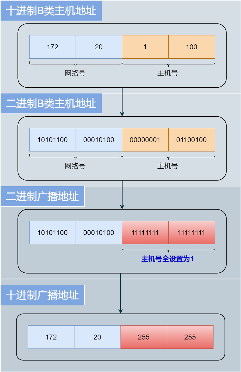
Broadcast Address
The broadcast address in an IP address is when all the host number bits are 1, which sends data packets to all hosts in the same subnet. For example, the broadcast address for a Class B host address 172.20.1.100 is 172.20.255.255.
IP Multicast
Multicast is used to send packets to all hosts in a specific group.
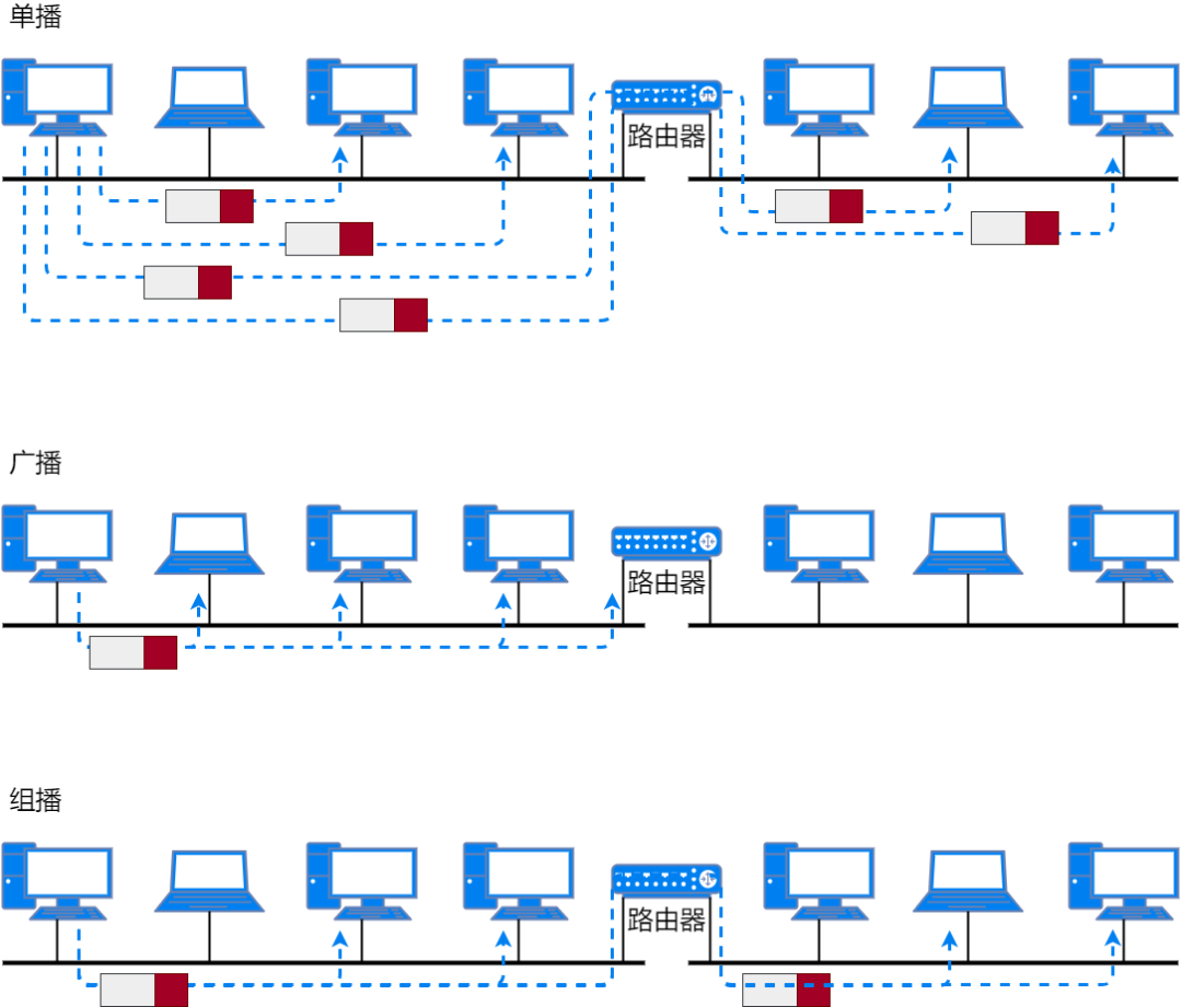
Multicast uses Class D addresses. Therefore, IP addresses that start with “1110” are multicast addresses. The remaining 28 bits are the group number for the multicast. The multicast address range is 224.0.0.0 ~ 239.255.255.255, where 224.0.0.0 ~ 224.0.0.255 can achieve multicast within the same subnet and send multicast packets to all group members across subnets.
Subnet Mask
In the early days, network addresses used a fixed-length network bit method, which caused a lot of waste of IPv4 addresses. Now the length of subnet addresses can vary, and a code is also needed to obtain the subnet address, so that routers can forward data packets. This identifier is called subnet mask.
The subnet mask is represented in 32 bits of binary, with the network address part of the IP address set to 1 and the host address part set to 0. In other words, the number of bits in the subnet address determines how many bits in the subnet mask are set to 1, while the rest are set to 0. For convenience, every 8 bits is grouped and separated by a “.”, then converted to decimal.
For example: the subnet mask for 201.20.100.25 is 255.255.255.0, which can be used to calculate its subnet address.
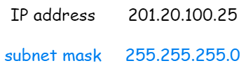
By performing a logical AND operation between the subnet mask and the IP address, the subnet address of this IP address can be obtained.

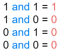
AND Operation
The binary numbers of the IP address and subnet mask are calculated bit by bit. The result is 1 only when both the IP address and the mask are 1. In all other cases, the result is 0.
Another way to represent an IP address is to append the number of bits in the network number after each IP address, separated by a “/”. For example: 201.20.100.25 can be represented as 201.20.100.25/255.255.255.0 or 201.20.100.25/24.
CIDR and VLSM
To solve the problem of IP address waste, in addition to using subnet masks, CIDR and VLSM technologies are also used.
CIDR, which stands for Classless Inter-Domain Routing, allows arbitrary length segmentation of the network number and host number in an IP address. It has two functions:
-
To aggregate multiple subnets into a larger subnet;
-
To summarize routing table IP addresses, reducing the load on the routing table.
VLSM, which stands for Variable Length Subnet Mask, can further subnet Class A, B, and C addresses to make full use of IP addresses.
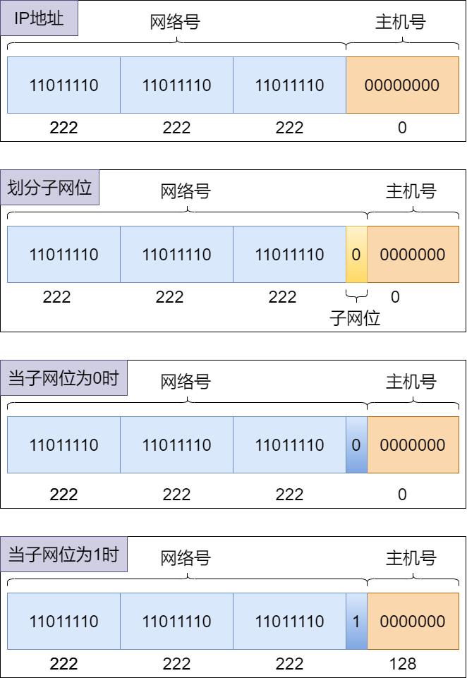
For example, if a company has 100 computers, under the previous method, it could only allocate one Class C address 222.222.222.0. However, VLSM can divide a Class C address into multiple subnet addresses, then allocate one that can accommodate slightly more than the number of computers needed by the company, thus achieving reasonable use of IP addresses.
-
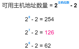
Calculating the subnet that accommodates 100 computers: use the number of bits in the host number to calculate the number of available host addresses in the subnet. When the host number has 7 bits, there are 126 available host addresses, which can accommodate 100 computers.
-
Calculating the subnet address: When the host number has 7 bits, the network number has 32 – 7 = 25 bits, which means
222.222.222.0/24borrows one bit from the host bits as the subnet bit, so the subnet mask is255.255.255.128. The usable subnet is222.222.222.0/25.
-
222.222.222.0/25Subnet Details:
Difference Between CIDR and VLSM
CIDR is when the host number borrows bits from the network number, aiming to aggregate several networks into a larger network and increase the number of subnet hosts;
VLSM is when the network number borrows bits from the host number, aiming to divide a standard network into several subnets and reduce the number of subnet hosts.
Public Address and Private Address
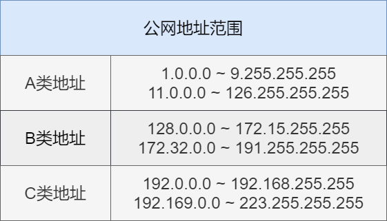
IP addresses are divided into public addresses and private addresses. Public addresses are used on the Internet, while private addresses are used in local area networks.
Public addresses are allocated by Internet NIC and are used to access the Internet directly.
Private addresses are a reserved range of IP addresses. They are only used within local area networks and cannot be used on the Internet. However, private addresses can be converted to public addresses via NAT technology to access the Internet.
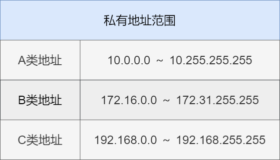
Public IP addresses are unique within the Internet, while private IP addresses only need to be unique within the same local area network. Having the same private IP in different local area networks will not affect usage.
IP Routing
IP routing is the operation of forwarding data based on IP addresses. When a data packet arrives at a router, the router queries the routing table based on the destination address of the data packet and forwards the packet according to the query result; this process is called IP routing.
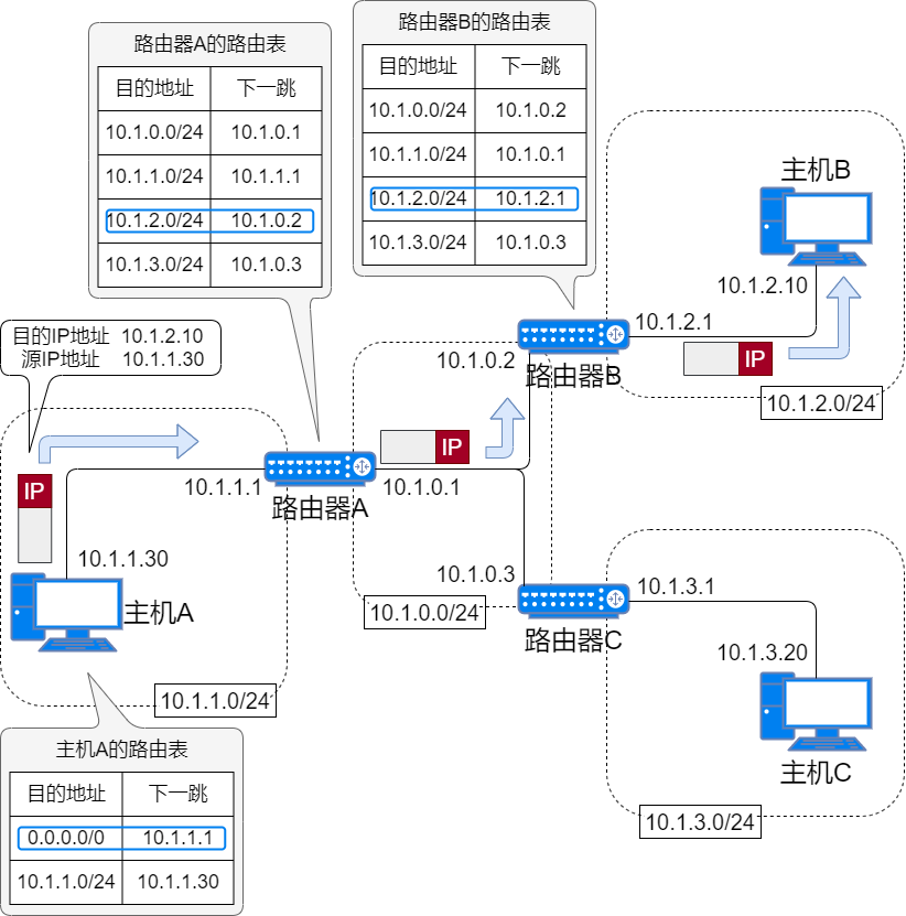
Routing Table
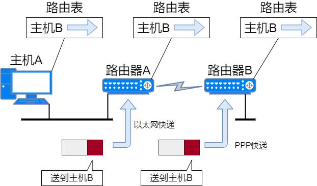
To send the data packet to the destination node, all nodes maintain a routing table. The routing table records which router the IP data should be sent to in the next hop. The IP packets will be transmitted over various data links based on this routing table.
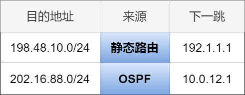
There are two ways to generate routing tables: one is manually set, known as static routing; the other is automatically refreshed by routers exchanging information, known as dynamic routing.
Next Hop
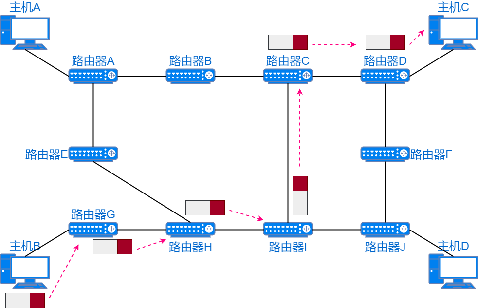
Hop refers to a segment in the network. IP packets are forwarded in hops through the network, determining the next hop path for the IP packets in each segment.
A hop refers to a segment of the broadcast domain in the data link, meaning a segment that can directly reach connected hosts or router interfaces without going through a router.
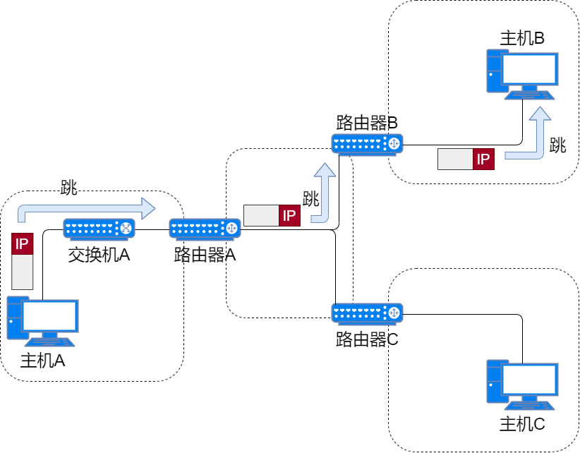
IP data packets are like parcels, while delivery trucks are like data links. Parcels cannot move by themselves; they must be carried and transferred by delivery trucks. Each delivery truck can only deliver parcels to a certain range. Each different segment’s parcels will be carried and transported by their corresponding delivery trucks. The working principle of IP is similar.
Types of Routing Entries
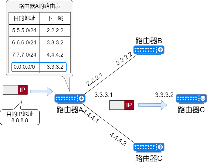
Default Route
The default route is an entry in the routing table that can match any address. All data packets can use the default route for data forwarding. The default route is 0.0.0.0/0 or default.
Host Route
“IP address/32” is called a host route, which is a routing entry in the routing table pointing to a single IP address or hostname. For example, 192.168.153.15/32 is a host route, indicating that all bits of the entire IP address will participate in routing.
Loopback Address
IP addresses starting with 127 are loopback addresses, and the loopback interface can be understood as a virtual network card. When using a loopback address, the data packet is directly retrieved by the host’s IP layer without going through the link layer or reaching the network. It is generally used to check whether the network services running on the host are functioning properly.
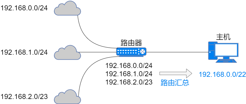
Route Summarization
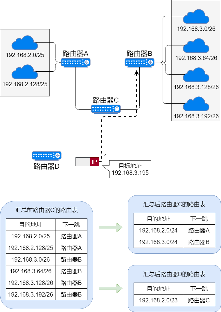
Route summarization is mainly to reduce routing entries by aggregating routable routes into one large network.
The larger the routing table, the more memory and CPU are required to look up the routing table, and the longer it takes, resulting in decreased performance in forwarding IP data packets. To build a large-scale, high-performance network, it is necessary to minimize the size of the routing table.
IP Fragmentation and Reassembly
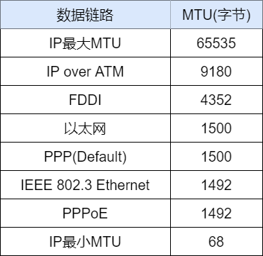
Different Data Links Have Different MTUs
Each data link has a different maximum transmission unit (MTU), and the IP at the network layer is the upper layer of the data link. IP uses fragmentation to mask the differences in data links, enabling interoperability between different data links. From the perspective of the layer above IP, it can completely ignore the MTU of each data link and only needs to receive data packets according to the length sent by the source IP address.
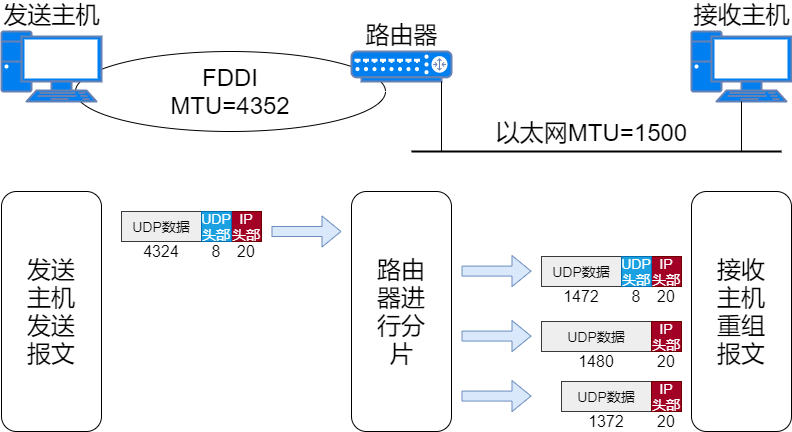
Fragmentation and Reassembly of IP Packets
When an IP data packet exceeds the data link MTU, it cannot be sent directly, so the host or router will perform fragmentation on the IP data packet.
After fragmentation, the IP data will only be reassembled at the destination host, and will not be reassembled while passing through routers.
Path MTU Discovery
The fragmentation mechanism has two shortcomings:
-
It burdens the processing performance of routers;
-
In fragmented transmission, if any fragment is lost, the entire IP data packet becomes invalid.
To solve this problem, Path MTU Discovery technology is used. The path MTU refers to the maximum MTU value between the sending host and the receiving host that does not require fragmentation, meaning the smallest MTU among all data links in the path. Path MTU discovery allows the sending host to fragment the data packet according to the path MTU value before sending it, avoiding fragmentation processing at intermediate routers.
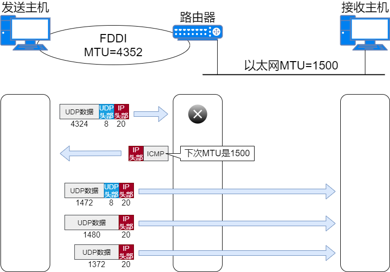
The working principle of Path MTU discovery is as follows:
-
When the sending host sends an IP data packet, it sets the fragmentation prohibited flag in the header to 1. Based on this flag, routers in the path will not fragment even if they receive a large packet that needs to be fragmented; instead, they will drop the packet and send an ICMP unreachable message back to the sending host with the MTU value of the data link.
-
The sending host processes the data packet based on the received MTU value and sends the IP data packet to the same destination host. This repeats until the data packet is sent to the destination host without receiving any further ICMP messages; it is then assumed that the last MTU reported by the ICMP message is an appropriate MTU value. The MTU value can be cached for about 10 minutes; during this time, the recently obtained MTU is used, and after 10 minutes, the path MTU discovery is performed again.
The above example is for UDP. If it is in the case of TCP, the maximum segment size (MSS) is calculated based on the path MTU size, and then data packets are sent based on this information. Therefore, in TCP, if Path MTU discovery is used, the IP layer will not fragment anymore.
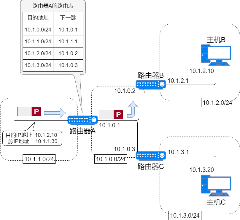
Router Layer 3 Forwarding Principle
Routers have multiple ports, each connected to different data links. They forward packets by identifying the network number of the destination IP address and then consulting the routing table. Only routing entries that match will be forwarded; unmatched entries will be dropped.
How do routers perform Layer 3 forwarding?
When a router receives a data packet, it executes the following steps:
-
It performs decapsulation on the data packet.
By decapsulating, it checks the destination IP address in the network layer header.
-
It looks for matching routing entries in the routing table.
To find matching routing entries, the destination IP address of the data packet must be bitwise AND with the subnet addresses of the routing entries, and then the result is compared with the subnet address of the routing entry. If they match, the entry corresponds to the destination IP address. After performing this operation and comparison with all routing entries, one or more matching routing entries may be found; if none are found, the data packet will be discarded.
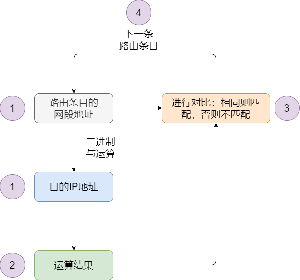
Routing Entry Lookup Flowchart -
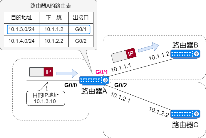
It selects the routing entry with the longest mask from multiple matches.
If there are multiple routing entries in the routing table that match the destination IP address of the data packet, the router will select the routing entry with the longest mask length; this matching method is called the longest match principle.
For example, if the network address for 10.1.3.10 matches both 10.1.3.0/16 and 10.1.3.0/24, the longer match of 10.1.3.0/24 should be chosen.
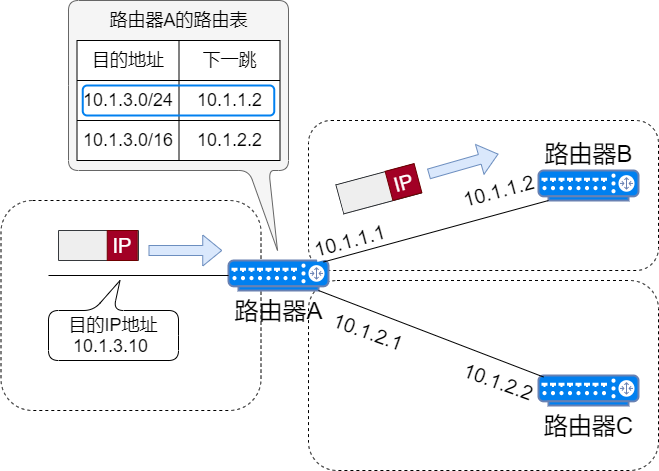
Longest Match Principle -
It forwards the data packet according to the corresponding routing entry.
The routing entry contains the next hop and outgoing interface. When the router finds the corresponding routing entry, it sends the data packet through the outgoing interface to the next hop device.
ARP
Once the IP address is determined, IP data packets can be sent to that target address. However, in actual communication, it is also necessary to know the MAC address corresponding to each IP address.
The Address Resolution Protocol, abbreviated as ARP, is the protocol used to query the corresponding MAC address based on the destination device’s IP address.
Working Principle of ARP
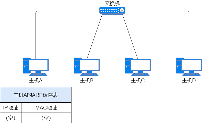
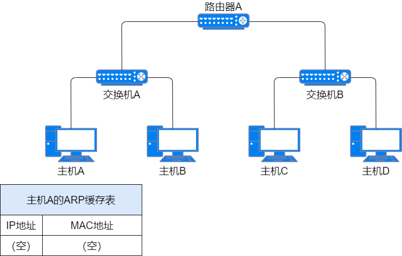
When Host A sends data to Host C within the same subnet but does not know Host C’s MAC address.
-
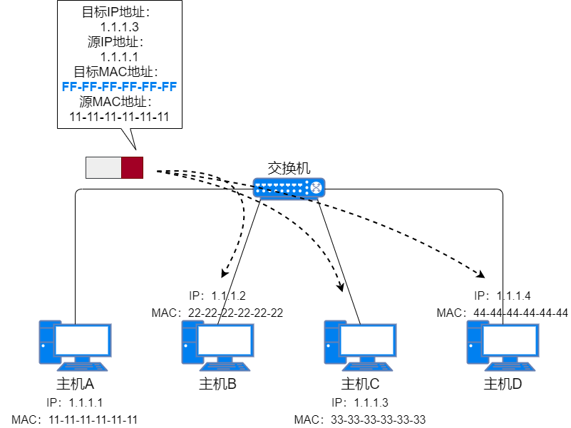
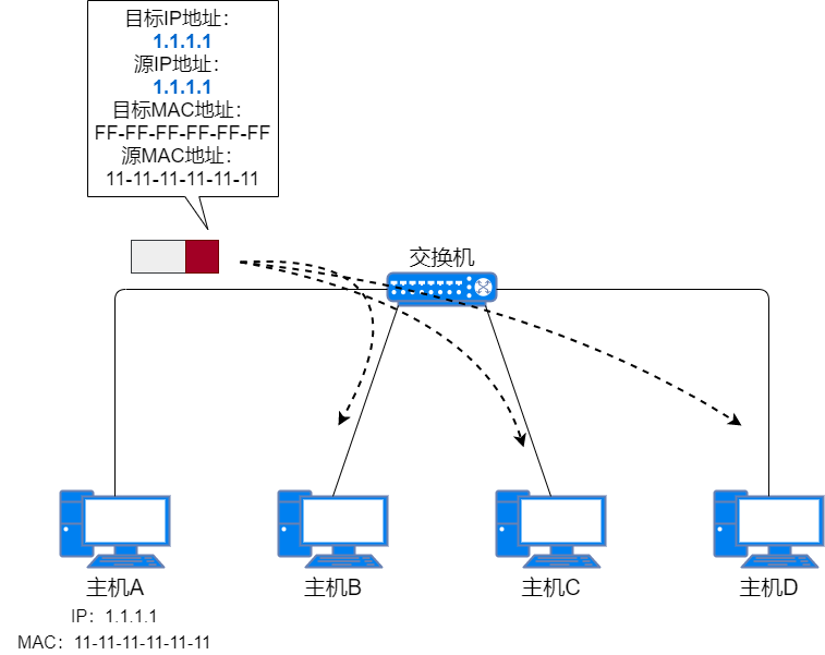
ARP Request: Host A sends a broadcast message with Host C’s IP address as the destination IP address and the broadcast MAC address as the destination MAC address within the same subnet. This message is called the ARP Request Packet.
The layer 2 switch does not check the IP address and sends the message to all ports except the receiving port based on the destination MAC address.
ARP Request Packet -
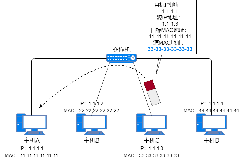
ARP Response: Host C discovers that the destination IP address is its own IP address, so it sends a response packet to Host A with its own MAC address and IP address as the source MAC address and source IP address, and Host A’s MAC address and IP address as the destination MAC address and destination IP address. This message is called the ARP Response Packet. Other hosts receive Host A’s ARP request packet but do not respond because the destination IP address is not their own IP address.
When Host A sends the ARP broadcast request packet, the layer 2 switch already has an entry for Host A’s MAC address. When the switch receives the unicast ARP response packet from Host C, it sends the packet through the corresponding port and records Host C’s MAC address and corresponding port in the MAC address table.
ARP Response Packet -
Update ARP Cache Table: After Host A receives the ARP response packet, it records Host C’s IP address and MAC address in the ARP cache table. The next time it sends data to Host C, it directly encapsulates the cached destination MAC address.

Updating ARP Cache Table
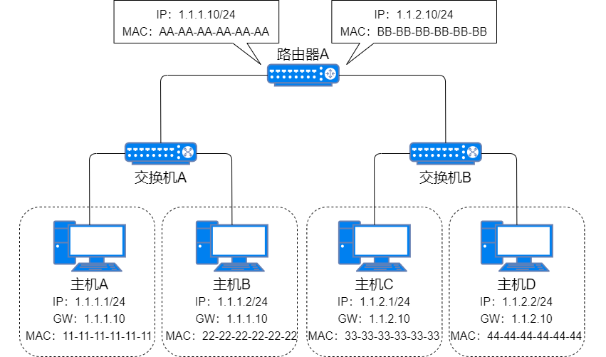
When Host A sends data to Host C in a different subnet, but does not know Host C’s MAC address.
-
Host A uses Host C’s IP address to query ARP. ARP finds that Host C is not in the same subnet and needs to go through the default gateway (the next hop address of the default route), but does not have the gateway’s MAC address;
Default Gateway -
Host A first caches the data to be sent to Host C, then sends an ARP request packet, using the gateway’s IP address as the destination IP address to send the ARP broadcast request packet;
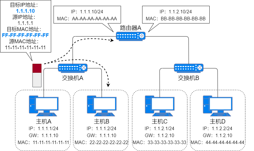
Gateway ARP Request Packet -
After the router receives the ARP broadcast request packet, it adds Host A’s MAC address and corresponding port to its MAC table and finds that the destination IP address is requesting its own MAC address, so it unicast sends the ARP response packet;

Gateway ARP Response Packet -
After Host A receives the ARP response packet, it encapsulates the data to be sent to Host C with the gateway MAC address as the destination MAC address;
Host A Sending Data to Host C -
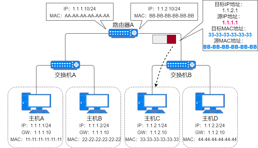
After the router receives the packet, it checks the destination IP address to see if it is sending to Host C, then queries the routing table to send data from the corresponding port. Since it does not have Host C’s MAC address, the router sends an ARP request packet, replacing the source MAC address and source IP address with the MAC address and IP address of the sending port;
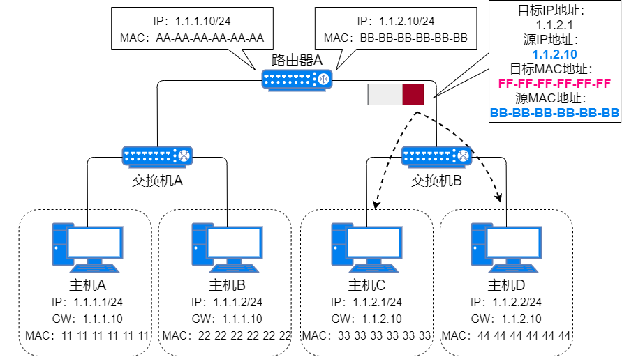
Host C’s ARP Request Packet -
Host C receives the ARP request packet, adds the router’s port and MAC address to its MAC address table, and unicast sends the ARP response packet;
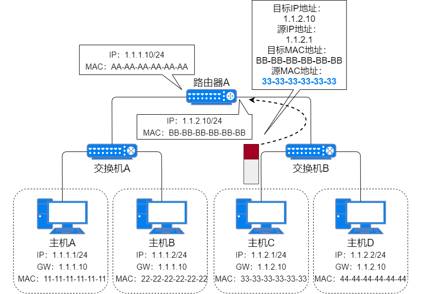
Host C’s ARP Response Packet -
After the router receives Host C’s MAC address, it adds it to its MAC address table. It then re-encapsulates the packet sent from Host A to Host C, using its own MAC address as the source MAC address and Host C’s MAC address as the destination MAC address, and sends it to Host C;

ARP Proxy Sending Data -
Host C receives the data sent by Host A, and the sending process ends.
When Host C sends a reply packet to Host A, the process is the same as when Host A sends data to Host C.
ARP Proxy
If the ARP request is sent from a host in one network to another host in the same subnet but not on the same physical network, a device with proxy ARP functionality connecting them can respond to the request. This process is called proxy ARP.
The proxy ARP function masks the separated physical networks, allowing users to operate as if they are on the same physical network.
Gratuitous ARP
Gratuitous ARP is a special type of ARP request that does not find the corresponding MAC address through IP, but sends a gratuitous ARP request when a host starts up, which requests the MAC address of its own IP address.
The difference from a normal ARP request packet lies in the target IP address in the packet. The target IP address in a normal ARP packet is another host’s IP address, while in a gratuitous ARP request packet, the target IP address is its own IP address.
The functions of gratuitous ARP are:
-
To serve as a notification. It sends a broadcast packet without needing a response, just to inform other hosts of its own IP and MAC addresses.
-
To detect IP address conflicts. If a host sends a gratuitous ARP request and receives an ARP response, it indicates that there is already a host using that IP address in the network.
-
To update other hosts’ ARP cache tables. If the host changes its network card, but other hosts’ ARP cache tables still retain the original MAC address, the gratuitous ARP packet can be used to update other hosts’ ARP cache tables.
ICMP
IP provides a best-effort service, meaning it tries its best to send data packets to the destination address. It does not verify whether the destination host has received the data packets and cannot guarantee service quality.
ICMP (Internet Control Message Protocol) is a protocol that provides such functionality. The main functions of ICMP include confirming whether IP packets are successfully delivered to the destination address and notifying the reasons for discarding IP packets during transmission.
ICMP messages are transmitted via IP like TCP/UDP, but the function of ICMP is not a supplement to the transport layer; it should be regarded as a network layer protocol.
The ICMP header encapsulation fields are as shown in the following figure.
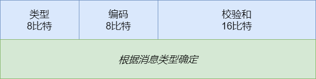
By judging the values of the type field and the code field, we can determine the type of ICMP message. The common types and code values of ICMP messages are shown in the following figure.
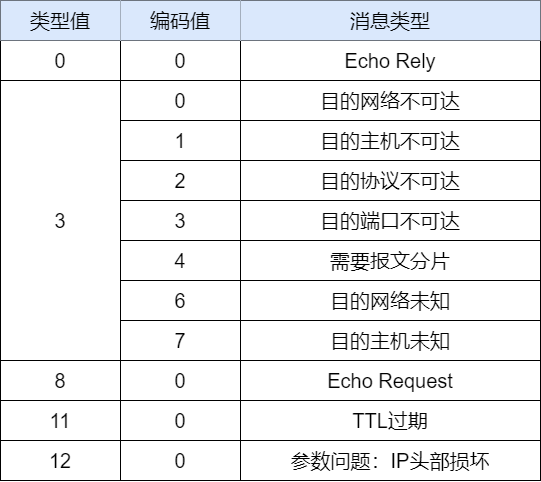
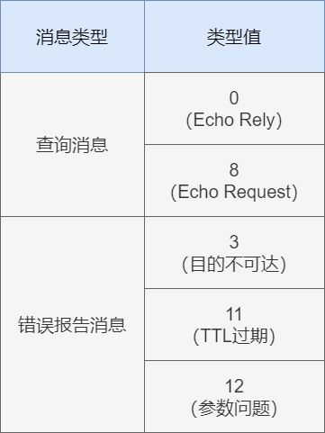
Functionally, ICMP messages are divided into two categories: one is error messages that notify the reasons for errors, and the other is query messages used for diagnostics.
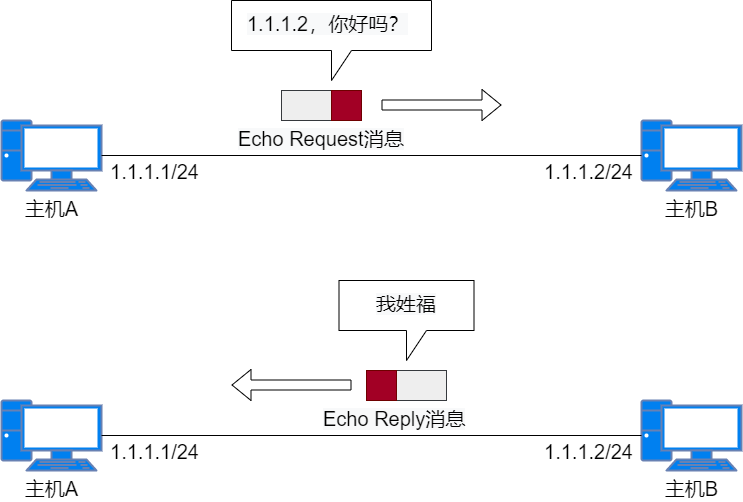
ping
The commonly used ping tool tests network layer connectivity through ICMP messages. The source host sends an Echo request message, and the destination host responds with an Echo reply message, indicating that the network layer communication between the two hosts is normal. The ping command can also be used to determine whether the target host is enabled.
Appendix
IPv4 Header
IP provides the simplest service: to achieve data forwarding from the source to the destination. It does not establish a connection with the receiving party before transmitting data and does not guarantee the reliability of transmission; it only provides a best-effort service.
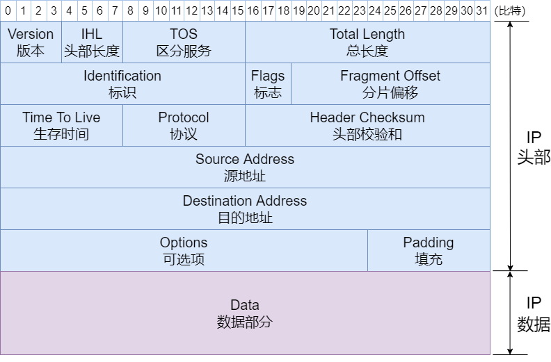
During IP communication, what is transmitted is an IP packet, which consists of an IP header and data. The IP header contains the necessary information to control packet forwarding. By examining the structure of the IP header, we can gain a detailed understanding of IP’s functionality.
What is a byte? What is a bit?
Bit, in English named bit, also called 位. It is the smallest unit in binary, and a bit can either be 0 or 1.
Byte, in English named Byte. A byte consists of eight bits.
-
Version (Version)
The field length is 4 bits, indicating the version number of IP. The version number for IPv4 is 4, so this field’s value is also 4. Common version numbers include IPv4 and IPv6.
-
Header Length (IHL: Internet Header Length)
The field length is 4 bits, indicating the size of the IP header, measured in 4-byte (32 bits) units. For an IP packet without optional fields, the header length is 5, meaning 20 bytes (4 × 5 = 20).
-
Type of Service (TOS)
The field length is 8 bits, used to indicate whether the data should be expedited or precisely transmitted, and whether congestion was encountered during transmission.
-
Total Length
The field length is 16 bits, indicating the total byte count of the IP header and data combined. The maximum length of an IP packet is 65,535 bytes.
-
Identification (ID)
The field length is 16 bits, used for fragmentation and reassembly. The identification value is the same for the same fragment and different for different fragments. Typically, each time an IP packet is sent, its value increments. Additionally, even if the ID is the same, if the destination address, source address, or protocol differs, they will be considered different fragments.
-
Flags
The field length is 3 bits, indicating fragmentation information. The specific meanings of each bit are shown in the table below.
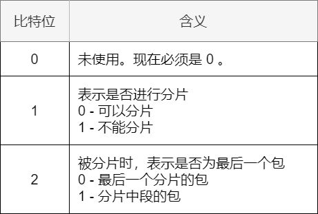
Meaning of Flag Bits -
Fragment Offset (FO)
The field length is 13 bits, indicating the position of the fragment in the entire data packet. Its function is to tell the device reassembling the fragments how to reorder the data packet.
-
Time to Live (TTL)
The field length is 8 bits, indicating the number of routers the data packet can pass through. Each time it passes through a router, TTL decreases by 1; when it becomes 0, the packet is discarded to prevent it from being transmitted indefinitely in the network.
-
Protocol
The field length is 8 bits, indicating the protocol used by the upper layer of IP. Common upper layer protocols for IP include TCP and UDP.
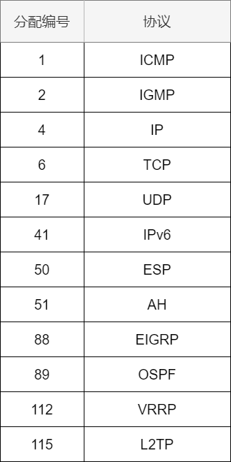
Upper Layer Protocol Numbers -
Header Checksum
The field length is 16 bits, used to verify whether the header of the data packet has been damaged. Devices will discard packets that fail the checksum. IPv6 eliminates the header checksum field, relying on the upper layer’s TCP or UDP to verify whether the protocol is correct.
-
Source Address
The field length is 32 bits (4 bytes), indicating the sending IP address.
-
Destination Address
The field length is 32 bits (4 bytes), indicating the receiving IP address.
-
Options
This field is rarely used and has been eliminated in the IPv6 protocol.
-
Padding
In cases where there are optional fields, if the header length is not a multiple of 32 bits, the field is padded with 0s to adjust it to a multiple of 32 bits.
-
Data
The IP data field is used to store data. The header of the upper layer protocol is also treated as data.
Reference Materials:
IP Basic Knowledge “Complete Package”, 45 Images Taken Away – Xiao Lin Coding
TCP/IP Illustrated, Volume 1: Protocols – W. Richard Stevens
Network Basics – Tian Guo
Visual TCP/IP – Takashi Takeshita