The communication distance of wireless modules is an important indicator, and how to maximize effective communication distance has always been a puzzling question for many. This article provides some explanations based on debugging experience and methods for selecting and using antennas, hoping to assist engineers in quickly debugging communication distances.
1. Types of Antennas
With the advancement of technology, many manufacturers have launched various ready-made antennas to save R&D time. However, if engineers make inappropriate choices, it can not only fail to achieve the desired effect but also waste a lot of time and cost on troubleshooting, which is counterproductive. This article will introduce several commonly used antennas and provide design suggestions based on practical experience in engineering for reference.
Next, we will introduce the common types of antennas:
(1) On-board PCB Antenna: Made from PCB etching, it is cost-effective but has limited performance, good adjustability, and can be used in large quantities for Bluetooth and WiFi wireless communication modules.
(2) SMT Patch Antenna: Commonly made of ceramic, it occupies a small area, has high integration, is easy to replace, and is suitable for products with space constraints, but this type of antenna is slightly more expensive and has a narrower bandwidth.
(3) External Rod Antenna: Good performance, no debugging required, easy to replace, high gain, suitable for various terminal devices.
(4) FPC Antenna: Connected via a feed line, it allows for flexible installation, has high gain, and can typically be adhered to non-metallic enclosures using adhesive, suitable for products with high performance requirements and ample enclosure space.
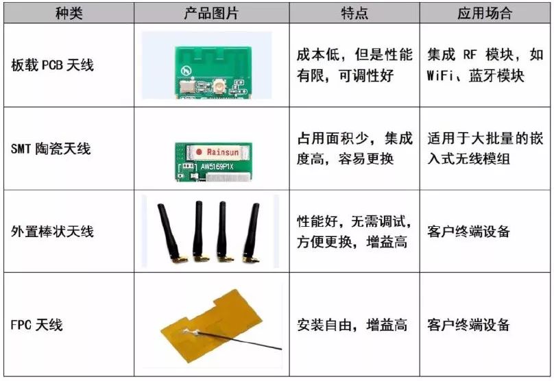
Figure 1 Common Antennas
The function of the antenna is to radiate radio frequency signals into free space. Choosing the right antenna greatly influences transmission distance. Antennas are very sensitive to their surrounding environment, and in many cases, even if the right antenna is chosen, the expected results may not be achieved. Since some customers are unclear about the factors to consider in antenna design, we provide some practical engineering design experience here to help customers better design their circuits and PCBs, increasing the chances of project success.
2. Choosing Antennas
The primary parameter affecting the communication distance of wireless modules is the transmission power. The transmission power of the wireless module and the corresponding ideal transmission distance can be found in the manual. After confirming that the transmission power meets the requirements, the selection of the antenna and its directionality should be considered.
First, the selection of the antenna:
The main indicators of antennas include the following: frequency range, standing wave ratio (SWR) or voltage standing wave ratio (VSWR), antenna gain, polarization mode, and impedance. The frequency range should be selected as needed; the standing wave ratio should preferably be less than 1.5; antenna gain also affects transmission distance; polarization can be linear or circular; impedance must match the output impedance of the wireless module, generally 50 ohms. Special attention should be paid to the standing wave ratio parameter; after purchasing the antenna, it is best to test the SWR using a network analyzer.
The table comparing the standing wave ratio with return loss and transmission power is shown in Table 1.
Table 1 Comparison of Standing Wave Ratio with Return Loss and Transmission Power
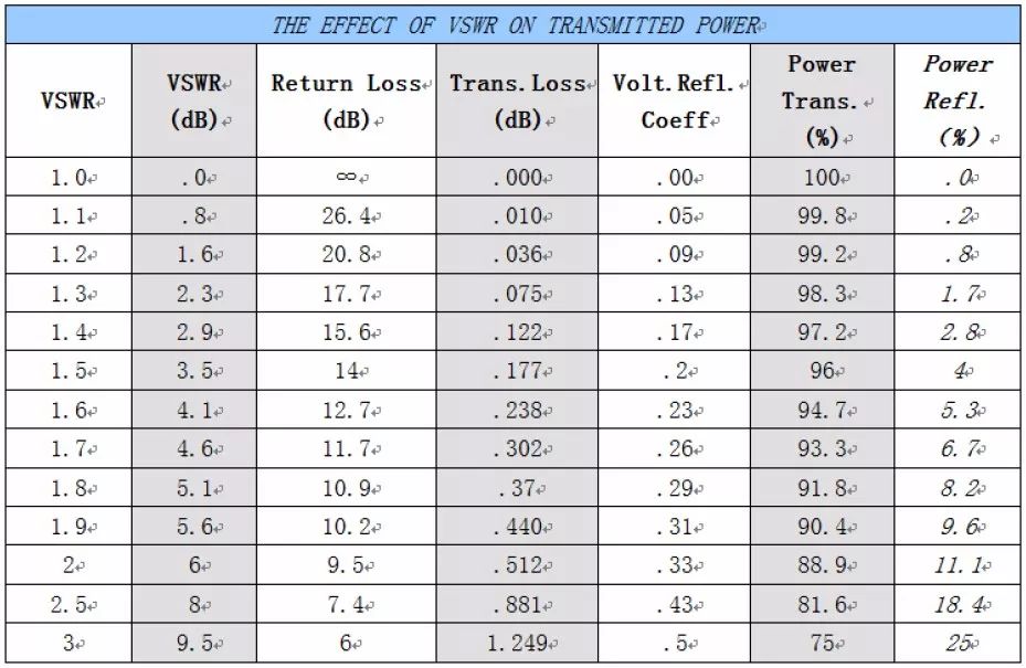
From the above table, it can be seen that when VSWR=1.5, the theoretical transmission power is 96%, and when VSWR=2, the transmission power is only 88.9%. Some antennas have a standing wave ratio index less than 2; when selecting antennas, it is best to choose one with a standing wave ratio less than 1.5 to achieve higher transmission power.
Secondly, the directionality of the antenna:
All antennas have directionality, which means that antennas have different radiation or reception capabilities in different spatial directions. The directionality of antennas is usually measured using radiation patterns. Figure 2 shows the radiation pattern of an antenna with a frequency range from 2400MHz to 2500MHz.
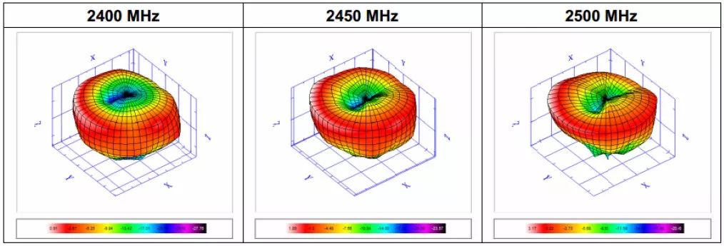
Figure 2 Three-dimensional Radiation Pattern of Antenna
When the antenna is placed vertically, the direction indicated by the deepest red color is the direction of the strongest radiation or reception capability of the antenna. Therefore, when installing the antenna, it should be oriented as much as possible towards the direction indicated in red to ensure good signal quality. Additionally, metal plates can shield signals, so there should be no metal planes in the direction of transmission or reception.
Some antenna manuals provide the radiation pattern using two-dimensional diagrams, divided into H-Plane and E-Plane, as shown in Figure 3.
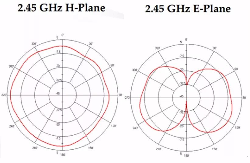
Figure 3 Two-dimensional Radiation Pattern of Antenna
When testing communication between wireless modules, the directionality of the antennas must be considered. When there are no obstructions in the communication space and the direction of the antennas corresponds to the strongest radiation direction, the communication distance can reach its maximum. If the antennas are improperly installed, it may shorten the communication distance or even result in a failure to communicate.
When engineers test wireless module communication, they often encounter weak signals, communication distances not meeting the specifications in the manual, or high packet loss rates. If it is confirmed that the wireless module itself is functioning properly, it is advisable to first test the performance of the antenna itself, and then test in the direction of strong signal radiation, which will yield better testing results.
3. Antenna Circuit Design
1. Matching Circuit Design
When designing the schematic, it is necessary to reserve a π-type network between the antenna and the module’s RF output pin. The impedance of the antenna is affected by factors such as PCB grounding, antenna installation, and surrounding metals. Reserving this network is to match it to 50 ohms when the antenna deviates significantly from the 50-ohm impedance.
X1, X2, and X3 are reactive components. If the antenna has a standard 50-ohm impedance, then X2 and X3 can be unsoldered, and X1 can be connected to a 220pF capacitor or a 0-ohm resistor. In the PCB design, these three components should be placed as close to the module’s RF output pin as possible, and the connecting transmission line should be short and straight. There should be no ground plane in the 1.5mm area around the matching components to reduce the impact of parasitic parameters on the matching circuit.
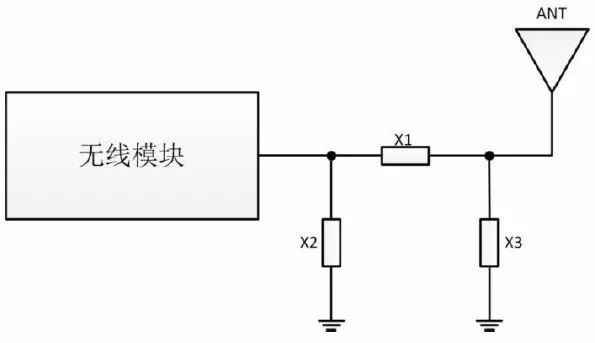
Figure 3 Matching Circuit
2. Microstrip Line Design
In PCB design, since most antennas and the module’s output impedance are 50 ohms, to minimize energy reflection during transmission, the PCB trace from the RF output pin to the antenna should be a 50-ohm microstrip line. The commonly used substrate is FR4 (dielectric constant of 4.2-4.6). Based on experience, when the line width is about 2.2 times the distance of the microstrip line from the reference layer, the characteristic impedance of the microstrip line is approximately 50 ohms. For specific designs, it is recommended to use microstrip impedance control tools (ADS, txline, etc.) for calculations and complete the microstrip line design through practical debugging. As shown in the figure below, the ground plane beneath the microstrip line must be complete, and multiple grounding vias should be added on both sides of the microstrip line.
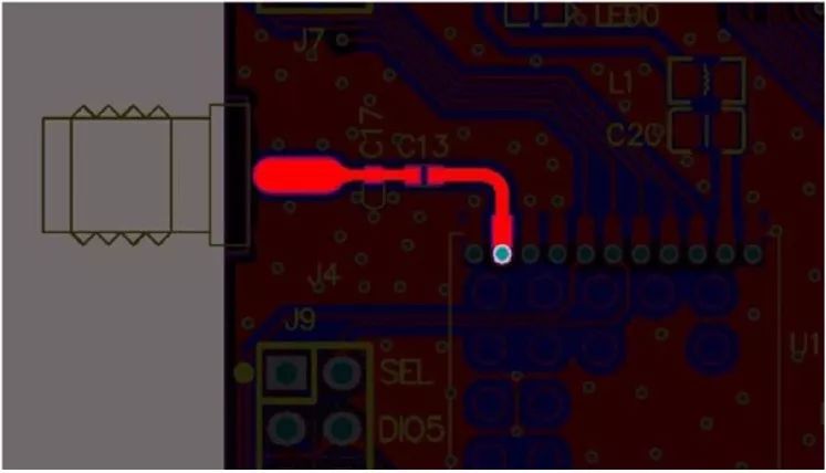
Figure 3 Microstrip Line
3. The Impact of Metal on Antennas
If there are metallic objects near the antenna, the metal can reflect electromagnetic waves, which not only affects the actual usable space of the antenna, increases the loss resistance, and reduces radiation efficiency, but also deteriorates the radiation performance of the antenna. When installing the antenna, pay attention to:
a: The antenna should be at least 5mm away from the battery;
b: The antenna should be at least 4mm away from the shielding case;
c: In cases where an enclosure is needed, do not use metallic paint or coatings on the surface of the enclosure.
Having read this, have you learned about the design tips for antennas in wireless products?
Related Reading:
From 4G to 5G: Future Trends in Antenna Technology
Professor Zhao Luyun from Xidian University: 5G New System Antenna Technology
Professor Zhang Yuping, an expert in the National Thousand Talents Program and IEEE Fellow: A Review of the Development of Packaging Antenna Technology
Interview with Dr. Huang Huanqu, Chief Antenna Expert at vivo, on 5G Antenna and Microwave Technology Trends
Discussion on Antenna Consistency, Stability, Reliability, and Measurement Methods
Comprehensive Understanding of Base Stations and Antennas by an Experienced Webmaster
From Parabolic to Phased Array: The Development History of Airborne Radar Antennas
Microwave RF Industry Professionals | Gather Here
[WeChat Technical Exchange Group for 10 Major Subfields]
The Microwave RF Network has established technical exchange groups in subfields such as RF, antennas, radar, millimeter waves, mobile RF, RFIC, power amplifiers, SDR, providing a platform for mutual exchange and promoting technological advancement.

Long press to recognize the QR code above to add the group owner as a friend, indicating: unit + technical direction, inviting you to join the corresponding technical group.