
Click the blue text to follow us

Today, we will analyze a classic microcontroller power supply circuit. The circuit schematic is shown in the figure below:
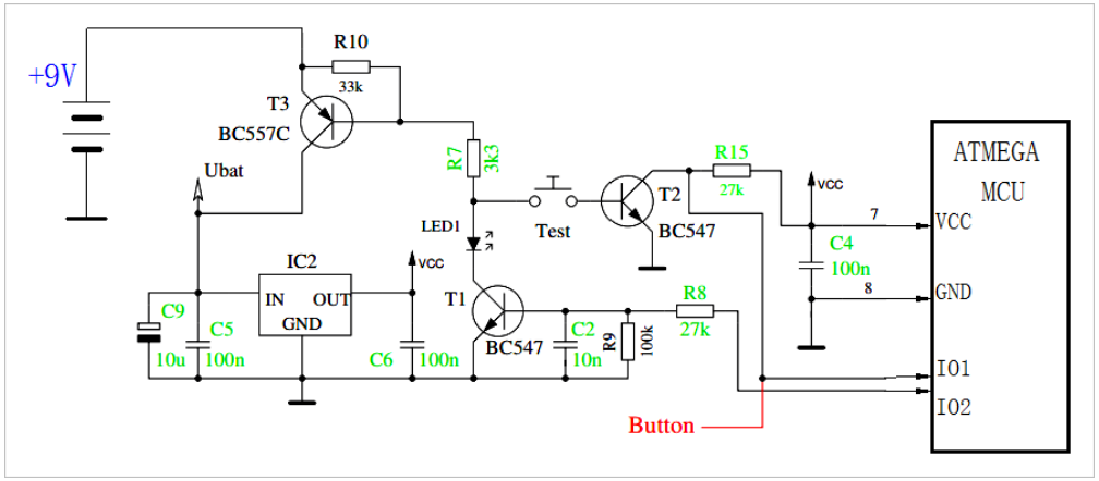
▲ Simplified switch circuit
Before powering the circuit, the switch “TEST” is open, and the microcontroller is not powered through VCC. At this time, the base of T1 is grounded through R9 (100k), putting it in the cutoff state. The base resistor R7 of T3 is connected to Test, and T1 is also in the cutoff state, so T3 is also in the cutoff state.
The power supply +9V is isolated by T3 and not loaded onto the voltage regulator chip IC2, keeping the output VCC low.
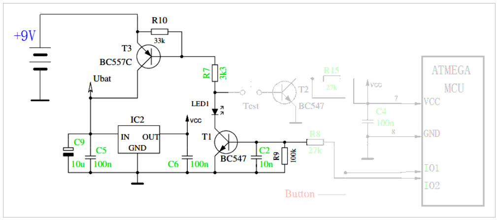
▲ Circuit in off state
Pressing the button “TEST” starts the circuit, and the base of T3 is grounded through R7, Test, and the b-e of T2, causing T3 to conduct. At this point, +9V is applied to the voltage regulator chip IC2 through T3. The output VCC of IC2 is applied to the microcontroller.
After the microcontroller starts working, it outputs a high voltage through IO2, allowing T1 to conduct through R8. Even if Test is released, the base of T3 can still be grounded through R7, LED1, and T1, achieving power self-locking.
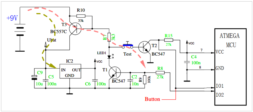
▲ Pressing TEST starts the circuit
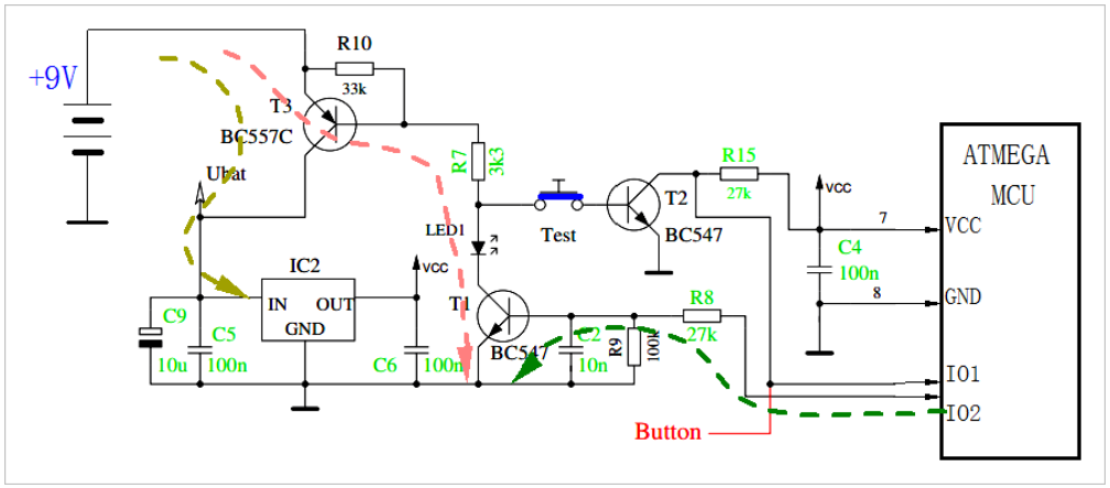
▲ After the circuit starts, the MCU provides the base voltage of T1, thus maintaining T3 in the conducting state
After that, the microcontroller software can make the IO2 port return to a low level, causing T1 to cut off, thereby turning off T3.
Based on the IO1 port, the switch state of T2 can be read to determine whether the user has pressed the function key. After determining that the user has pressed Test, wait until the user releases Test before setting IO2 to a low level.
Software functions can also implement automatic delay power-off, thereby reducing power consumption.


|
|
|
|
|
|
|
|
|
|
||
|
|
|
|
|
|
||
|
|
||
|
|

↑ Scan the code to sign up for consultation ↑