Learn How to Use Proteus for PCB Design

Learn How to Use Proteus for PCB Design

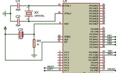
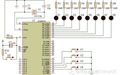
Currently, using Keil C51 and Proteus for microcontroller system development has become the first choice for many microcontroller enthusiasts. The combination of Keil C51 and Proteus allows for software design and hardware simulation debugging of microcontroller systems, which can greatly shorten the development cycle and reduce development and debugging costs. Once the simulation debugging is … Read more
Creating a Digital Clock Thermometer with AT89C52 in Proteus

Creating a Digital Clock Thermometer with AT89C52 in Proteus

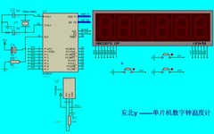
1. Introduction In this tutorial, we will use Proteus software to demonstrate how to design and simulate a digital clock thermometer based on the AT89C52 microcontroller. We will cover hardware circuit design, software programming, and simulation testing using Proteus. 2. Project Overview The digital clock thermometer is a device that integrates time display and temperature … Read more

Step-by-Step Guide to DIY Remote-Controlled Car Simulation with Proteus

Step-by-Step Guide to DIY Remote-Controlled Car Simulation with Proteus

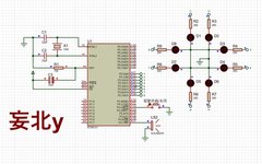
This example will explain how to DIY a remote-controlled car. The remote-controlled car can execute related actions based on commands from the remote control. The hardware system of the remote-controlled car mainly includes the main microcontroller minimum system circuit, indicator light circuit, motor drive circuit, power circuit, remote control mode display circuit, independent key circuit, … Read more

Alarm System with Rotating Light Using 8051 Microcontroller

Alarm System with Rotating Light Using 8051 Microcontroller

1. Introduction The alarm system with rotating light project is a typical embedded system application that combines sound alarms and visual indicators. It is widely used in various scenarios such as security monitoring, emergency evacuation, traffic signals, and entertainment devices. Based on the 8051 microcontroller, it provides an integrated sound and visual alarm solution, enhancing … Read more

The Evolution of the Multimeter

The Evolution of the Multimeter

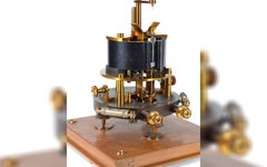
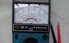
The first pointer meter used to detect current was called a galvanometer, invented in 1820. When used in conjunction with a Wheatstone Bridge, it can compare an unknown resistance and voltage to known voltages and resistances, thereby measuring related voltages, currents, and resistances. This method of measurement in the laboratory is time-consuming and labor-intensive, making … Read more

How to Measure Random Noise Signals Using a Multimeter

How to Measure Random Noise Signals Using a Multimeter

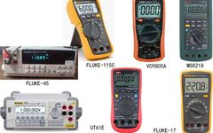
The digital multimeter is a powerful assistant for measuring electrical signals. Although it is called a “universal” meter, its common functions are limited to measuring voltage, current, and resistance. Voltage and current measurements also include AC and DC ranges. In addition, some multimeters can measure inductance, capacitance, continuity, diode forward voltage, transistor current gain, counting … Read more

How to Use a Digital Multimeter

How to Use a Digital Multimeter

China’s High-Speed Rail Goes Global, Railway College Achieves the Future -Click the blue text above to follow the official WeChat account of Xi’an Railway Technician College’s Academic Affairs Office- Today, let’s learn how to use a multimeter with the students from Class 34 of the Fall 2020 Pre-College Mechanical Inspection.First, the teacher presented the knowledge … Read more

Digital Multimeter Fault Analysis and Handling

Digital Multimeter Fault Analysis and Handling

★ Digital multimeters are widely used in people’s daily life and study due to their simplicity, digital display, ease of operation, and strong anti-interference capabilities. This article briefly describes the common faults encountered during the use of digital multimeters and provides some daily handling methods. 1. Several Common Fault Analysis Methods for Digital Multimeters 1.1 … Read more

Using a Multimeter to Measure Current and Resistance

Measuring DC Voltage with a Multimeter (Task: Measure 9V Battery, 1.5V Battery) (1) When measuring DC voltage, identify the positive and negative terminals (the red probe connects to the positive terminal “+”, and the black probe connects to the negative terminal “-”). Connect the multimeter in parallel to the circuit being tested. Before measuring the … Read more

Design Principles and Measurement Calculation Methods of Multimeters

Design Principles and Measurement Calculation Methods of Multimeters

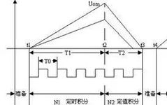
This article mainly introduces the design principles of digital multimeters and the calculation methods for average value and true RMS value, explaining the defects of the average value calculation method and the calculation method for true RMS value of AC signals superimposed with DC signals. It emphasizes the necessity of using multimeters with true RMS … Read more