1. Introduction
In this tutorial, we will use Proteus software to demonstrate how to design and simulate a digital clock thermometer based on the AT89C52 microcontroller. We will cover hardware circuit design, software programming, and simulation testing using Proteus.
2. Project Overview
The digital clock thermometer is a device that integrates time display and temperature measurement functions. This project aims to design a digital clock thermometer with the following features:
(1) Using the AT89C52 microcontroller as the control core. (2) Using the DS18B20 as the temperature sensor. (3) The display interface uses an LCD screen. (4) Low power design, suitable for long-term operation.
3. Hardware Design
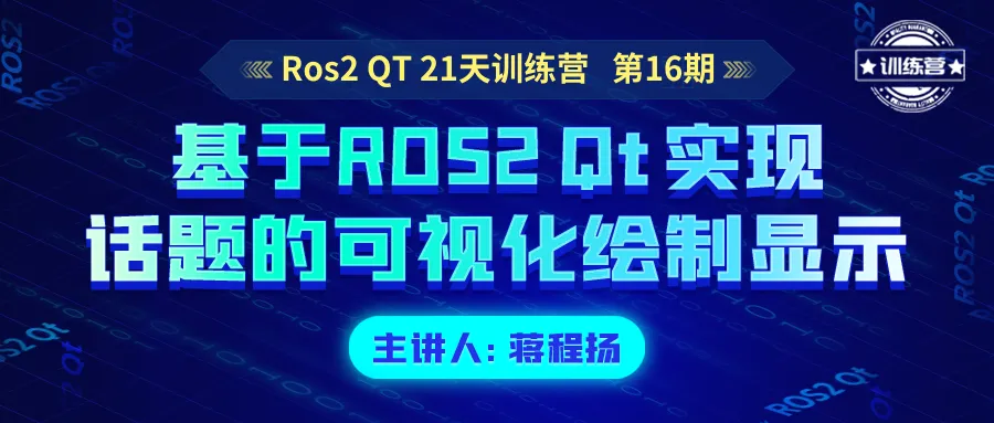
The hardware design includes the selection of the microcontroller, peripheral circuit design, and connections to the sensor and display.
1. Microcontroller Selection
We chose the AT89C52 microcontroller because it has the following advantages: (1) Rich I/O interfaces. (2) Built-in 8-bit CPU and at least 8KB of programmable Flash memory. (3) Operating frequency up to 12MHz.
2. Peripheral Circuit Design
Here are the main points of the peripheral circuit design:
Crystal oscillator: Using XTAL1 and XTAL2 as the clock source for the microcontroller, with a frequency of 12MHz.
Power supply: VCC provides a 3.3V power supply to ensure stable system operation.
I/O interfaces: Ports P1 and P3 are used for connecting to external devices, such as the temperature sensor and LCD screen.
Reset circuit: R1 is a 4.7kΩ resistor, connected to the microcontroller’s RST (reset) pin.
4. Proteus Simulation
We will use Proteus software to simulate the designed circuit and verify its functionality.
1. Create a New Project
Create a new project in Proteus and add the AT89C52 microcontroller component.
2. Design the Schematic
According to the hardware design requirements, draw the circuit schematic, including the microcontroller, sensor, display, and peripheral circuits.
Clock Signal: The 12MHz clock signal provided by the crystal oscillator drives the microcontroller.
Power Supply: The microcontroller is connected to a 3.3V power supply via VCC.
Reset Circuit: Ensure that the microcontroller can reset correctly when powered on or in case of an anomaly.
I/O Ports: Used to connect external devices, such as the temperature sensor and LCD screen.
Serial Communication: Serial data exchange with external devices through the RXD and TXD pins.
Interrupt Function: Respond to external interrupts through the INT0 and INT1 pins, improving system response speed.
Timer: Use timers for time control, such as timed reading of temperature or refreshing the display.
3. Simulation Settings
1) Microcontroller Core AT89C52: This is the core of the entire system, an 8-bit microcontroller with 8KB of internal memory and rich I/O ports.
2) Clock Circuit XTAL1 and XTAL2: These two pins are the clock input pins of the microcontroller, usually connected to a crystal oscillator to provide a reference clock frequency.
FREQ=12MHZ: This indicates that the frequency of the crystal oscillator is 12MHz, which is the operating frequency of the microcontroller.
3) Power Supply VCC: The positive power input of the microcontroller, usually 5V or 3.3V, shown as 3.3V in the diagram.
GND: Represents the ground, which is the 0V reference point.
4) Reset Circuit RST: Reset pin, usually needs to be connected to VCC through a resistor and a capacitor to form a reset circuit.
R1=4.7k: This resistor may be used for the reset circuit, connected in parallel to the RST pin and VCC.
5) Memory Expansion ALE: Address Latch Enable, used for address latching when expanding external memory.
EA: External Access, used to select whether the microcontroller uses internal or external memory.
6) Input/Output Ports P1.0 to P1.7: Eight I/O pins of Port 1, which can be used to connect various peripherals.
P3.0 to P3.7: Eight I/O pins of Port 3, usually used for more complex communication and control functions.
7) Special Function Pins RXD (P3.0) and TXD (P3.1): Represent receiving and transmitting data, used for serial communication.
INT0 (P3.2) and INT1 (P3.3): Represent external interrupt 0 and external interrupt 1, used to respond to external events.
T0 (P3.4) and T1 (P3.5): Represent the inputs for Timer 0 and Timer 1, used for timing and counting.
8) Temperature Sensor DS18B20: A commonly used digital sensor for measuring temperature, communicating with the microcontroller via the One-Wire protocol.
9) Display Module LCD: Liquid crystal display used to show time and temperature information.
10) Other Components R2: Used for current limiting or voltage division. 8k2: Refers to an 8.2kΩ resistor.
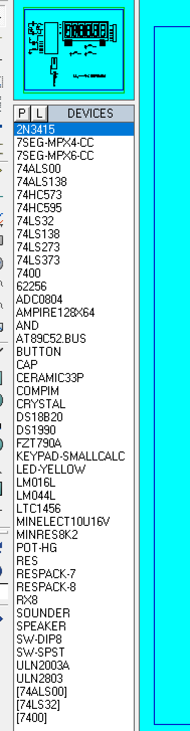
4. Simulation Run
Run the simulation, observe the working state of the circuit, and perform necessary debugging.
5. Programming Implementation
Include header files
#include "reg51.h"Define keys
sbit key0 = P1^0;Delay function (The delay function takes an unsigned integer parameter dd and decrements until 0 to achieve the delay. The actual delay time depends on the microcontroller’s clock frequency and compiler optimization.)
delay(unsigned int dd){ while(--dd);}Display function (The disp function is used to display a character on a four-digit display. It takes an unsigned char type parameter aa.)
Inside the function, by setting different bits of port P2, we select the segments of the display, and then send the number or character to be displayed via port P0. The display is achieved by controlling the on/off of each segment, where each segment represents a stroke on the display.
disp(unsigned char aa){ P2 = 0xff; P0 = aa; P2 = 0x7f; delay(1000); P2 = 0xff; P0 = 0x06; P2 = 0xbf; delay(1000); P2 = 0xff; P0 = 0x5b; P2 = 0xdf; delay(1000); P2 = 0xff; P0 = 0x4f; P2 = 0xef; delay(1000); P2 = 0xff; P0 = 0x66; P2 = 0xf7; delay(1000); P2 = 0xff; P0 = 0x6d; P2 = 0xfb; delay(1000); }Main loop (The main function is the entry point of the program. It initializes a counter aa and then enters an infinite loop.)
Inside the loop, the program checks if key0 is pressed (i.e., key0 is low). If the key is detected, the value of aa is incremented. Then, the disp function is called to display the current value of aa.
main(){ unsigned char aa=0; while(1) { if(!key0) aa++; disp(aa); }}Program Logic
The logic of the program is to increment a value by pressing a key and display this value on the display. Each key press increases the value of aa by 1, and the new value is immediately displayed on the display.
Notes (1) This code does not consider key debouncing; in practical applications, debouncing logic may be needed to avoid false triggering. (2) The display code in the disp function is hard-coded, which means it can only display specific characters. If different numbers or characters need to be displayed, the internal code of the function needs to be modified. (3) The accuracy of the delay function depends on the microcontroller’s clock frequency, and this implementation does not consider the impact of compiler optimization.
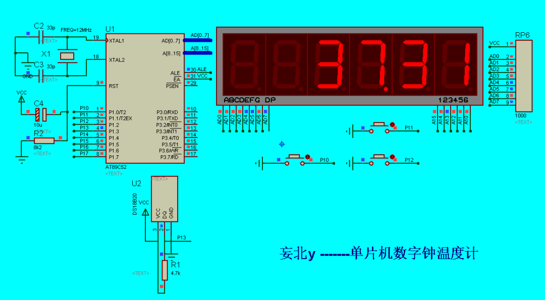
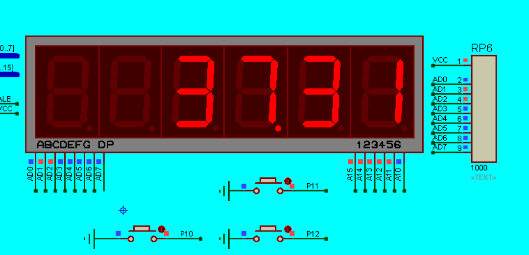
6. Result Analysis
Through the Proteus simulation, we can observe the real-time temperature display function of the digital clock thermometer. Below are screenshots of the simulation results:

From the image, it can be seen that the key parts of the microcontroller, such as the crystal oscillator, power supply, and I/O ports, are correctly connected. The LCD screen can correctly display the temperature values read from the DS18B20.
7. Summary and Outlook
This project demonstrates how to use Proteus software to design and simulate a microcontroller-based digital clock thermometer. Through practice, we verified the feasibility of the design and laid the foundation for further hardware implementation.