Protocol (specification, including software and hardware) — Implementation –> Code (protocol stack)Protocol (data frame) — Encapsulation –> Protocol stack (code — application layer settings) –> Application layer4. Application Layer3. Network Layer (labeling, from where to where, addressing)2. MAC Layer (link), data frame format structure1. Physical Layer
- Coordinator, only one is allowed, low power consumption is not supported. Scans the surroundings during creation, then has a different address
- Routing, forwarding, joining, creation is not supported, low power consumption is not supported. Network expansion
- Node (terminal), low power consumption — sleep mode, forwarded by 1, 22, 3 addresses are assigned by 1 (0X 00 00, 65535 total)
Although Zigbee has a lower transmission rate, its response speed is very fast, generally taking only 15ms to transition from sleep to active state, and only 30ms for nodes to join the network. Future IoT devices will also have higher requirements for response speed, which is precisely Zigbee’s advantage.
The 802.15.4 category may be the largest standard for low-rate WPANs. It has many subcategories. The 802.15.4 category was developed for low-rate monitoring and control applications and low-power uses to extend battery life. The latest updates and enhancements to the basic standard are 802.15.4a/b, with 802.15.4c applicable in China, 802.15.4d in Japan, 802.15.4e for industrial applications, 802.15.4f for active (battery-powered) RFID applications, and 802.15.4g for Smart Utility Networks (SUNS) to monitor smart grids. All these special versions use the same basic radio technology and protocols defined in 802.15.4a/b.
The 802.15.4 standard defines the physical layer (PHY) and media access control (MAC) layer of the open system interconnection (OS) model for network operation. The PHY defines the frequency, power, modulation, and other wireless conditions of the link. The MAC defines the format of data processing. The remaining layers define additional measures for processing data and related protocol enhancements, including final applications.
IEEE 802.15.4e has been authorized to define MAC amendments to the existing standard 802.15.4-2006, which adopts channel hopping strategies to improve support for the industrial market, enhancing robustness against external interference and persistent multipath fading. On February 6, 2012, the IEEE Standards Association Board approved IEEE 802.15.4e, concluding all work of Task Group 4e.
802.15.4 supports two network topologies, namely single-hop star or multi-hop peer-to-peer topology when communication lines exceed 10m. However, the logical structure of the peer-to-peer topology is defined by the network layer.
ZigBee Protocol Stack
The ZigBee protocol stack is divided into four layers: physical layer (PHY), media access control layer (MAC), network layer (NWK), and application layer (APL). Each layer has its specific functions and protocols.
ZigBee Features
- Low Power Consumption: ZigBee devices are designed for low power consumption, allowing for long-term operation.
- Low Cost: ZigBee modules are relatively inexpensive, suitable for large-scale applications.
- High Reliability: ZigBee uses CSMA/CA (Carrier Sense Multiple Access/Collision Avoidance) mechanism to ensure reliable data transmission.
- Security: ZigBee supports AES-128 encryption to ensure data transmission security.
The basic principle of Zigbee’s transmission rate is that the Zigbee network uses the IEEE802.15.4 standard to define data transmission rates. The IEEE802.15.4 standard defines seven different modulation and demodulation methods, with data transmission rates of 250 kbps, 40 kbps, 20 kbps, 10 kbps, 5 kbps, (5) kbps, and (2) 5 kbps. Therefore, the maximum data transmission rate of the Zigbee network can reach 250 kbps.
How to Improve Zigbee Transmission Rate
To improve the Zigbee transmission rate, first determine the number of nodes in the network, the structure of the network, and the distance between nodes. If the number of nodes in the network is small, a higher data transmission rate, such as 250 kbps, can be used; if the number of nodes is large, a lower data transmission rate can be used to reduce interference in the network. Additionally, the distance between nodes in the network will also affect the data transmission rate; the closer the nodes are, the higher the data transmission rate.
How to Set Zigbee Transmission Rate
Setting the Zigbee transmission rate requires specific software, such as the XBee Network Manager (XNM), which can help users configure the network structure and set the data transmission rate. Additionally, network management software can be used to monitor nodes in the network and check network performance.
Zigbee also supports other lower data transmission rates, such as 40Kbps in the 915 MHz band and 20Kbps in the 868 MHz band.
Specifically, the Zigbee physical layer uses Direct Sequence Spread Spectrum (DSSS) technology for data transmission, improving data transmission efficiency and reliability through bit-symbol mapping, O-QPSK modulation, and pulse shaping. This technology allows Zigbee to provide stable communication performance at low rates while maintaining low power consumption.
In some cases, using a baud rate of 115200, the actual rate may only be 11.25Kbps.
2.4GHz Band:
The maximum data transmission rate is 250kbps.
In practical use, due to various factors, the transmission rate is usually between 20-30kbps.
868MHz Band (European Standard) :
The maximum data transmission rate is 20kbps.
In some cases, the transmission distance can reach 300 meters.
915MHz Band (US Standard) :
The maximum data transmission rate is 40kbps.
Although the transmission rate is low, its transmission distance can reach between 30 meters to 75 meters.
Zigbee Physical Layer Uses Direct Sequence Spread Spectrum (DSSS) Technology
What Factors Most Commonly Affect Actual Transmission Rate in Zigbee Communication?
In Zigbee communication, the actual transmission rate is affected by various factors. The following points are the main influencing factors:
- Signal Strength: Signal strength significantly affects the transmission rate of Zigbee. If the signal strength is insufficient, it may lead to packet loss and retransmission, thereby reducing the overall transmission rate.
- Transmission Distance: The transmission distance of Zigbee is also an important factor. Longer transmission distances require more relay nodes, which increases network complexity and potential delays, thus affecting the transmission rate.
- Network Topology: The network topology of Zigbee (such as star, tree, mesh, etc.) also affects its transmission rate. Different topologies handle data flow and routing differently, which may impact data transmission efficiency.
- Packet Size: Smaller packets can improve performance because they are easier to receive and process. For example, if the data packet sent by the user is less than 96 bytes, the best performance can be achieved.
- Network Traffic Density: Higher network traffic density can lead to increased collisions, thereby reducing reception rates and transmission rates. Therefore, under high traffic density, the transmission rate may significantly decrease.
- Mobility: The mobility of nodes can significantly affect Zigbee’s performance. When nodes move, link failures and routing failures become more frequent, leading to decreased reception rates, which in turn affects transmission rates.
- Interference: Interference from other wireless communication systems, such as WiFi, can also negatively impact Zigbee’s transmission rate. Interference elimination techniques can reduce this impact, but challenges still exist.
- Channel State Prediction and Rate Selection at the Physical Layer: By predicting channel states and selecting rates at the physical layer, Zigbee’s transmission rate can be optimized under different conditions. This method can maximize throughput and improve network efficiency.
The actual transmission rate of Zigbee is influenced by various factors, including signal strength, transmission distance, network topology, packet size, network traffic density, mobility, interference, and channel state prediction and rate selection at the physical layer.
The Connectivity Standards Alliance (CSA) announced the release of Zigbee PRO 2023, the next version of the Zigbee PRO standard, which brings new security features reflecting the importance of device security and interoperability in IoT development.Providing Zigbee development tools and solutions sets standards.
Zigbee PRO 2023 is backward compatible, allowing users to utilize the latest protocol stack in Zigbee 3.0 product certification. To learn more about Zigbee PRO 2023, visit silabs.com/zigbee for more information on Silicon Labs’ support for Zigbee.
Some advantages of IEEE 802.15.4.
First, DSSS spread spectrum, the typical transmission rate of IEEE802.15.4 (specifically the 2.4GHz version used by Zigbee) can reach 2Mbps, where one chip is one “0” or “1”, which is one bit. The well-known Zigbee air interface rate is only 250kbps, but in fact, early Atmel and Cypress released 2Mbps Zigbee chips, which did not become a communication standard. DSSS spread spectrum means that our conventional 1 byte (byte) is 8 bits, but in communication (including wireless and wired communication), encoding rules are added, for example, serial communication has start and stop bits, making one byte equal to 10 bits. The DSSS spread spectrum of IEEE802.15.4 converts 32 bits into 1/2 byte, meaning one byte equals 64 bytes. We often say serial ports are 8/10 encoding, PCIe 3.0 is 128/130 encoding, but IEEE802.15.4 is 1/8 encoding. This approach significantly reduces transmission efficiency, but improves anti-interference capability. A typical example is based on Shannon’s theorem, using 1/8 encoding requires less energy to transmit over longer distances. For instance, WiFi at 20dBm power has a transmission distance of only a few dozen meters, while Zigbee at 20dBm can reach hundreds of meters or even over a kilometer.
A typical 20dBm product can transmit over 1KM.
Second, the benefits brought by CSMA/CA. The air interface rate of Zigbee is 250kbps, but if there are too many Zigbee devices in the same frequency band, this rate cannot be achieved. It can be understood that Zigbee devices automatically reduce the rate, but the cumulative communication throughput of all Zigbee devices in the same frequency band is also close to 250kbps. This is different from Bluetooth, which uses a frequency hopping mechanism, meaning the transmission rate is fixed, but if Bluetooth encounters too many similar devices in the area, it will also experience severe packet loss, and the transmission rate will significantly decrease. Additionally, it should be noted that Zigbee, Bluetooth, and WiFi in the 2.4G band will interfere with each other.
Third, low power transmission. The sleep principle of Zigbee differs from that of Bluetooth, Lora, and other IoT protocols. Zigbee’s sleep mode must rely on the parent device, which cannot sleep. Messages sent to the sleeping device are transmitted to the parent device, and the sleeping device actively reads messages from the parent device upon waking. Other IoT protocols typically use time synchronization methods to send messages to sleeping devices just as they wake up. In this regard, Zigbee has a very low maintenance cost. However, there is still an issue: when the parent device saves messages for child devices, if it receives a wake-up message from a child device, it needs to determine within 352us whether it has saved messages for the child device. If it has, it must set the Pending flag in the MAC ACK. Many ZigBee chips accomplish this quick determination through special hardware circuits. Because the parent device also has CSMA/CA limitations when transmitting messages to child devices, it will not immediately send messages to child devices. However, if the child device receives the MAC ACK after 352 seconds, it will determine whether to sleep immediately or wait a while. Immediate sleep may result in missing messages delayed by CSMA/CA from the parent device, while not sleeping immediately may cause the child device to wait unnecessarily, wasting energy. On the Zigbee device side, the most power-consuming part is data reception, as the RX RF circuit must remain on, and the longer it is on, the more power it consumes. In contrast, transmitting signals consumes less power, although the peak power is high, the duration is only a few milliseconds, at most just over 4 milliseconds, consuming little energy.
Second, directly jump to the application layer, which is the so-called APS and ZCL protocols.
Let me first talk about the APS layer protocol:
A Zigbee chip often supports several sensors and functions running in parallel. For example, some lighting fixtures and switches integrate multiple sensors; it is reasonable for some switch devices to have at least 2-3 switch paths. Therefore, the APS layer introduces a concept called Endpoint, similar to ports in TCP/IP, where one port corresponds to one service. ZigBee can also be simply understood as one port corresponding to one service or one peripheral. For example, a Zigbee switch needs to provide circuit on/off control services, with one port corresponding to one relay, allowing each port to be controlled independently, leading to the common Zigbee multi-way switch where each path can be controlled independently without affecting the others. Of course, there are a few special ports in Zigbee, such as port 0 for ZDO services, which manage Zigbee device networking, including device addition and identification. Then there is the Green Power port 242, which is used for interaction between regular Zigbee devices and Green Power devices. The application layer ports can use numbers 1-240 freely.
Each port will also have a Profile, which can be translated as “profile”; we can call it “port profile”. Only ports with the same Profile can establish communication; otherwise, it is like talking to a duck. Typically, a Zigbee device can integrate multiple ports, and if a Zigbee device has multiple ports with different Profiles, then this Zigbee device is like a “polyglot”. However, in the current market applications, the “Home Automation” profile (0x0104) is very common, while others like SE, ZLL, etc., are rarely used.
Each port also has a Device ID and several Cluster IDs. The Device ID is the type of device for that port, such as lighting fixtures, electric curtains, and smart sockets, which are identified based on this Device ID. Since a Zigbee device can have multiple ports, it is common for a Zigbee device to be both a socket and a sensor, thus being multifunctional.
Then there are Clusters, which can be translated as “clusters”, but it may be more reasonable to call them “function clusters”.
A “function cluster” is a collection of functions. For example, controlling the color of a light involves several methods such as color temperature control, color coordinate control, and color wheel control, while the state of the color can be represented by several physical quantities such as color coordinates, color saturation, and color temperature. These control methods and physical quantities are collectively referred to as “function clusters”. Moreover, different function clusters represent different functions; for example, temperature has two function clusters, one for system temperature (like CPU temperature) and one for sensor temperature. Here’s a joke about using the wrong function cluster: a mine detected a temperature rise to 90℃ and activated the spray system, but that 90℃ was the CPU temperature…
Function clusters are also divided into In and Out, which means input and output. This concept can be difficult for many beginners to understand. Here we need to divide Zigbee devices and Zigbee ports into two roles: “control end” and “execution end”. For example, a typical Zigbee remote control controls a Zigbee bulb. The remote control is the control end, and the bulb is the execution end. The remote control must have an Out cluster (output cluster) related to controlling the light, while the bulb must have a corresponding In cluster (input cluster).
Having discussed this, let’s talk about the ZCL protocol.
The ZCL protocol defines what the “control end” should do and what the “execution end” should do based on the characteristics of Zigbee ports. In the ZCL protocol, the Zigbee port is named “Client” for the control end and “Server” for the execution end, which is something many beginners find confusing. For example, a typical Zigbee gateway is a universal “control end”, and many gateways do not have the functionality of an “execution end”, so the gateway is a universal “Client”, while the controlled devices become “Servers”.
In fact, the relationship between the control end and the controlled end is based on function clusters. For example, a gateway is a universal control end when controlling devices, but if the gateway serves as an OTA upgrade service, it becomes a controlled end. This is because the gateway plays a file storage role during Zigbee device OTA upgrades, which can be understood as “the Zigbee gateway is the mobile hard drive for the Zigbee bulb, containing the upgrade files needed by the Zigbee bulb”.
Next, we have the “attributes” and “control commands” defined under the Zigbee clusters. Each cluster has several attributes (Attribute) and control commands (Specific Command). Attributes are fixed constants on Zigbee devices, usually used to represent the current state of the device, such as the brightness of a bulb, the on/off state of a switch, the current value and threshold of a sensor, and the current state of an alarm device. Within the same cluster, attributes are also divided into control end attributes and execution end attributes; basically, 99% of clusters only have execution end attributes, while clusters like OTA upgrade have control end attributes to indicate their current upgrade progress. Of course, Zigbee’s cluster specifications can be defined by the user, and one can define a large number of control end attributes and execution end attributes as desired. Zigbee attributes have several access methods: read, write, and actively report. Reading attributes means obtaining the current state of the device, while writing attributes means changing the device state. However, many Zigbee devices generally do not use the write attribute method to control devices for security reasons, but rather use control commands. Previously, a smart light made by “X Health X Vision” used the write attribute method for control, resulting in the light crashing and rebooting during frequent controls. Active reporting means that when the attribute value changes locally, it actively sends it to the target device, and active reporting is often used as a heartbeat packet for the device.
Next, we have control commands, which all have directional flags. Commands sent from the control end to the execution end are usually called Requests (request commands), while responses from the execution end are called Responses (response commands). Additionally, the execution end can also use Notify (notification commands) to synchronize messages to the control end. Using read/write attributes to control devices has many limitations, such as each attribute being a fixed-size constant, which cannot transmit complex information like variable-length messages or control with multiple parameters. In such cases, control commands must be used. For example, a typical Zigbee unlocking device has attributes representing the lock state, such as 0 for open and 1 for locked. If the attribute is simply written as 0 to unlock, once the command is intercepted by a hacker, it can easily unlock the door. However, if a control command is used to unlock, a dynamic password can be included in the control command, ensuring that only the control end and execution end have the encoding/decoding rules, significantly improving security.
Third, how should the Zigbee gateway be designed?
As mentioned earlier, the Zigbee gateway is a universal control end. Therefore, the Zigbee gateway should have the following functions:
1. The gateway can read and write any attribute on any device, regardless of which port or cluster the attributes are in, whether they are control end attributes or execution end attributes. The gateway can operate them. Moreover, the gateway can also set attributes with active reporting functions, allowing Zigbee devices to actively report attributes to itself.
2. The gateway can send any request command under any cluster and receive any response commands and notification commands under any cluster. Especially when the gateway receives response commands and notification commands, it needs to automatically reply with the correct acknowledgment message.
3. Support manufacture code. In the ZCL protocol specification, function clusters range from 0xFC00 to 0xFFFF, reserved for Zigbee device manufacturers to customize private protocols, such as infrared code learning, Modbus conversion, and other applications. The Zigbee Alliance allows manufacturers to define cluster specifications and use manufacture codes to mark them. Therefore, the Zigbee gateway must meet the principle of “not picky”, so the Zigbee gateway must be able to read and write attributes with manufacture codes and receive active reports of such attributes. It must also have the ability to send and receive control commands with manufacture codes.
————DSSS Spread Spectrum,Direct Sequence Spread Spectrum (DSSS): is a wireless communication technology with high anti-jamming capability, achieved by multiplying the data signal with a pseudo-random code, widely used in military communication and wireless networks.—In the 2.4GHz band, there are 16 channels with a rate of 250Kbit/s (or 62.5 K symbol/s), in the 915 MHz band, there are 10 channels with 40 Kbit/s (or 40 K symbol/s), and in the 868MHz band, there is 1 channel with 20 Kbit/s (or 20 K symbol/s). The ISM band has the characteristic of being globally available, which not only exempts 802.15.4 devices from frequency licensing requirements but also provides many companies with a rare opportunity to develop standardized products that can work anywhere in the world.While maintaining simplicity, 802.15.4 also attempts to provide design flexibility. An 802.15.4 network can select a working channel from 27 channels based on availability, congestion, and data rate. From an energy and cost efficiency perspective, different data rates can provide better choices for different applications. For example, some computer peripherals and interactive toys may require 250 Kbit/s, while many other applications, such as various sensors, smart tags, and household appliances, can be satisfied with a low rate of 20 Kbit/s.802.15.4’s low-rate, low-power, and short-distance transmission characteristics make it very suitable for supporting simple devices. In 802.15.4, 14 physical layer basic parameters and 35 media access control layer basic parameters are defined, totaling 49, which is only one-third of Bluetooth. This makes it very suitable for simple devices with limited storage and computing capabilities. In 802.15.4, two types of devices are defined: Full Function Devices (FFD) and Reduced Function Devices (RFD). Full Function Devices are required to support all 49 basic parameters, while Reduced Function Devices only need to support 38 basic parameters at minimum configuration. A Full Function Device can communicate with both Reduced Function Devices and other Full Function Devices and can operate in three ways: as a personal area network coordinator, coordinator, or device. In contrast, a Reduced Function Device can only communicate with Full Function Devices and is used for very simple applications.
Beacon Mode and Superframe Structure
An 802.15.4 network can operate in beacon-enabled or non-beacon-enabled modes. In beacon-enabled mode, the coordinator periodically broadcasts beacons to achieve synchronization with related devices and other purposes. In non-beacon-enabled mode, the coordinator broadcasts beacons irregularly and unicasts beacons to devices when they request them. The beacon-enabled mode uses a superframe structure, the format of which is defined by the coordinator, generally including an active part and an optional inactive part.
Data Transmission and Low Power Consumption
In 802.15.4, there are three different data transfers: from device to coordinator; from coordinator to device; and in peer-to-peer networks from one party to another. To highlight the low power characteristics, data transmission is divided into the following three methods:
Direct Data Transmission: This applies to all three types of data transfers mentioned above. It uses Carrier Sense Multiple Access with Collision Avoidance (CSMA-CA) or slotted CSMA-CA data transmission methods, depending on whether beacon-enabled or non-beacon-enabled mode is used.
Indirect Data Transmission: This only applies to data transfer from the coordinator to the device. In this mode, data frames are stored in the transaction processing list by the coordinator, waiting for the corresponding device to retrieve them. By checking the beacon frame from the coordinator, the device can find out if there is a data packet belonging to it in the transaction processing list. Sometimes, indirect data transmission may also occur in non-beacon-enabled mode. The same CSMA-CA or slotted CSMA-CA is used during the data retrieval process.
Guaranteed Time Slot (GTS) Data Transmission: This only applies to data transfer between devices and their coordinators, which can be from device to coordinator or from coordinator to device. In GTS data transmission, CSMA-CA is not required.
Mechanisms to extend device battery life or save power. Most mechanisms are based on beacon-enabled mode, mainly limiting the transmission and reception time of devices or coordinators, or putting them into sleep mode when there is no data transmission.It is predicted that UWB mesh networks will ultimately consist of “smart dust particles”, a type of micro radio that generates energy through nanotechnology windmills or photovoltaic cells. The application potential of UWB mesh networks is vast; the US military has already been testing UWB applications in telemetry, with the current main issue being cost, as the price of low-speed, low-power UWB chipsets is at least $20.
In contrast, Zigbee’s price target is only a few cents. The Zigbee Alliance believes that Zigbee chips will be ubiquitous, and their applications will extend far beyond telemetry and remote control.
====UWB technology is commonly used for precise positioning and seamless interaction between devices, and is an important feature for enhancing the ecosystem experience of Xiaomi’s flagship models.Xiaomi 17 Ultra appears in the Ministry of Industry and Information Technology, supporting UWB technologyUWB ultra-wideband technology is used for precise spatial awareness and device interconnection, but does not include satellite communication functions.Ultra Wide Band (UWB) technology is a wireless carrier communication technology that does not use a sine carrier but transmits data using nanosecond-level non-sinusoidal narrow pulses, thus occupying a very wide frequency spectrum.
Ultra Wide Band (UWB): From Precise Positioning to High-Speed Transmission, Unlocking a New Dimension of Wireless Communication
In the grand stage of mobile communication technology, every revolutionary technology has its unique mission. Bluetooth has changed the way devices connect with its convenient short-range connections, Wi-Fi has shaped modern life with its high-speed local area network access, and cellular networks support the vision of connecting everything with their wide coverage. However, beyond these mainstream technologies, Ultra Wide Band (UWB) technology is rising strongly. UWB is not a new concept; its technical research has a history of decades, but only in recent years, with its large-scale application in consumer electronics such as smartphones and wearable devices, UWB has truly unlocked a new dimension of wireless communication with its unique centimeter-level precise positioning and high-speed data transmission capabilities, bringing unprecedented imaginative space to IoT, augmented reality, and industrial automation.
UWB technology typically uses ultra-wide frequency bands from 3.1GHz to 10.6GHz. However, its fundamental characteristic is that it communicates by sending and receiving extremely narrow pulse signals, which usually last only nanoseconds or even picoseconds. This short pulse transmission method brings two key advantages. First, extremely narrow pulses, when expanded in the frequency domain, occupy a very wide frequency band, allowing UWB systems to achieve extremely high data transmission rates, theoretically reaching Gbps levels. Second, due to the extremely short duration of the pulses, UWB signals have a natural resistance to multipath effects. Even if the signal encounters reflections during propagation, the significant time delay between the reflected pulse and the main pulse allows the receiver to distinguish different paths based on the time difference, without suffering from signal distortion like narrowband systems.
It is precisely based on this unique pulse communication method that UWB technology exhibits unparalleled advantages in precise positioning. Its positioning principle mainly relies on Time of Arrival (ToA) or Time Difference of Arrival (TDOA). In ToA mode, device A sends a UWB pulse to device B, which immediately returns a pulse upon receiving it. Since UWB signals propagate at the speed of light, by accurately measuring the total time from sending to receiving and back, and subtracting the fixed delay of internal processing in the devices, the distance between device A and device B can be calculated with extreme precision. Because of the short duration of UWB pulses, the time resolution is extremely high, allowing distance measurements to achieve centimeter-level accuracy. This is fundamentally different from Bluetooth or Wi-Fi positioning, which relies on signal strength (RSSI) and is easily affected by environmental interference and multipath effects, with accuracy typically only at the meter level.
As a high-speed connection technology, UWB complements Bluetooth and Wi-Fi. Bluetooth is responsible for low-power, low-speed device discovery and pairing, Wi-Fi handles high-power, high-bandwidth internet access, while UWB can provide secure, private, and high-speed communication between devices after discovery. This multi-modal fusion communication architecture will bring users a seamless and smooth device interconnection experience.Another core advantage of UWB is its excellent anti-interference capability and security.UWB technology is rapidly expanding its applications across various fields. In the consumer electronics sector, Apple was the first to integrate UWB chips into devices like the iPhone, Apple Watch, and AirTag, using it as the core technology for the “Find” feature, providing users with an unprecedented precise locating experience.In the automotive industry, UWB is seen as the ideal technology for the next generation of digital car keys. Compared to traditional keyless entry systems, UWB digital keys can accurately identify the owner’s location and direction, automatically unlocking when the owner approaches the door and locking when the owner leaves, while effectively preventing relay attacks and other security vulnerabilities. In the industrial IoT (IIoT) field, UWB can be used for indoor high-precision positioning, such as real-time tracking of materials, equipment, and personnel in factory warehouses, optimizing production processes and improving safety management. In the healthcare sector, UWB can be used to monitor patients’ locations and activities, assist caregivers in management, and even has potential applications in non-contact vital sign monitoring.
Although standards like IEEE 802.15.4a/z provide specifications for the physical and MAC layers of UWB, compatibility issues may still exist in the protocol stack and application layer of UWB devices from different manufacturers, hindering seamless interconnection between devices of different brands. To address this, industry organizations like the FiRa Alliance are actively promoting the standardization and ecological construction of UWB technology to ensure that different devices can work together. Another challenge is power management. Although UWB has very low power consumption during pulse transmission, its overall power consumption still needs optimization in applications requiring continuous distance measurement to meet the long battery life requirements of battery-powered devices. Additionally, cost is an important consideration; as UWB chips are produced on a larger scale, their costs are gradually decreasing, but they still lag behind mature technologies like Bluetooth, which somewhat limits their popularity in low-cost devices.
Ultra Wide Band (UWB) technology, with its unique physical characteristics, breaks through the limitations of traditional wireless communication in positioning accuracy and data transmission rates, from centimeter-level precise positioning to high-speed data transmission, it is unlocking a new dimension of wireless communication. Although facing challenges such as standardization and cost, with the active promotion of industry giants and the increasingly complete industrial chain, UWB is transitioning from a niche technology to mainstream applications, forming a complementary synergy with technologies like Bluetooth and Wi-Fi to build a smarter, more efficient, and secure wireless interconnected world. The rise of UWB is not just a victory of technology but a profound re-recognition of the physical foundations of wireless communication, proving that even in seemingly saturated wireless fields, there is still vast innovative space waiting for us to explore.
Gai Shi Automotive Research Institute: UWB and Star Flash Representing In-Vehicle Communication Technology Begin to Restructure Automotive Data Interaction
In-vehicle communication technology is the “nervous system” of intelligent connected vehicles, enabling data interaction inside and outside the vehicle, supportingassisted/autonomous driving, vehicle-road collaboration, and intelligent services, driving the evolution of vehicles into mobile intelligent terminals.
In-vehicle communication is divided into in-vehicle bus communication and external wireless communication based on different connection forms, jointly building in-vehicle networks, vehicle-to-vehicle networks, and vehicle-to-cloud networks to achieve multi-channel information exchange.
In-vehicle bus communication (in-vehicle network) uses automotive wiring harnesses as carriers, connecting various domain controllers, gateways, and MCUs in the vehicle at different forms and rates. Depending on the transmission rate, in-vehicle networks can be divided into high-speed buses (in-vehicle Ethernet, in-vehicle Serdes, USB, etc.) and low-speed buses (CAN, LIN, FlexRay, MOST, etc.). Under the trend of domain-centralized architecture, in-vehicle bus communication is upgrading from the traditional CAN bus to in-vehicle Ethernet as the backbone network, combined with hybrid communication architectures using technologies like CAN-FD and FlexRay. In-vehicle Serdes is mainly used to meet the demand for high-speed video data transmission in in-vehicle systems, with main application scenarios including in-vehicle displays, infotainment systems, cameras, and LiDAR, which are essential for smart vehicles and have huge development prospects.
External wireless communication technologies can be divided into short-range wireless communication and long-range wireless communication based on transmission distance. Short-range wireless communication includes vehicle-to-everything (V2X), Bluetooth, Wi-Fi, UWB, Star Flash, and other communication technologies. V2X technology is currently dominated by LTE-V2X, and in the future, there will be a coexistence of multiple technologies, including 5G-V2X and LTE-V2X. UWB ultra-wideband technology, with its high positioning accuracy, strong anti-interference capability, and low power consumption, is applied in the field of automotive short-range wireless communication, currently mainly used for digital car keys and live detection radar, and in the future, it can also be used for automatic wireless charging, automatic payment, valet parking (AVP), and other scenarios, expected to become the ecological entry point for smart travel. Star Flash is a new generation of near-field wireless connection technology independently developed in China, integrating the advantages of Bluetooth, Wi-Fi, and other technologies, characterized by low latency, high reliability, precise synchronization, and high concurrency. Star Flash technology is currently being gradually verified for use in scenarios such as digital keys, active noise cancellation, wireless BMS, and ambient lighting, and is expected to gradually replace Bluetooth in the future.
Long-range wireless communication technologies consist of mobile communication technologies, microwave communication technologies, and satellite communication technologies. Currently, mobile communication is mainly based on 4G, gradually transitioning to 5G. In-vehicle satellite communication technology is mainly used to provide vehicle location monitoring and reporting, vehicle rescue, emergency calls, social entertainment, and other capabilities in off-road tourism scenarios such as deserts, gobi, and forests, with its commercialization process accelerating. The in-vehicle mobile internet network is composed of vehicle machines, signal base stations, cloud services, mobile device terminals, and satellite positioning systems. With the rise of cloud computing, big data, and AI intelligence, the cloud will greatly empower vehicles.
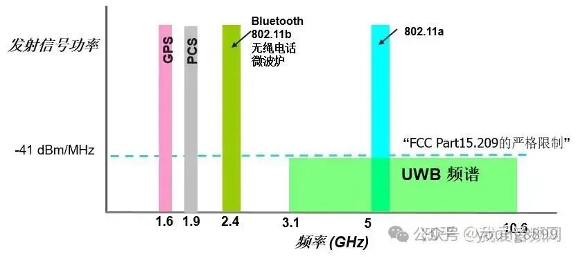 UWB technology has advantages such as low system complexity, low transmit signal power spectral density, insensitivity to channel fading, low interception capability, high positioning accuracy, and strong penetration capability, making it especially suitable for high-speed wireless access in dense multipath environments like indoors.UWB is not a new technology; it was first applied in military radar and communication applications, originally called “pulse radio”. Since 2002, the Federal Communications Commission (FCC) has authorized its unlicensed use, allocating it to the 3.1-10.6GHz band, occupying more than 500MHz of bandwidth.Traditional Global Navigation Satellite Systems (GNSS) can provide satellite positioning services, but satellite signals can be blocked by buildings, making indoor positioning impossible. Wi-Fi and Bluetooth typically determine location by receiving signal strength indicators (RSSI), only showing rough categories of “weak” or “strong” received signals, with positioning accuracy typically reaching only meter-level. UWB positioning has three technologies: TOF (Time of Flight), TDOA (Time Difference of Arrival), and PDOA (Phase Difference Of Arrival). Although this is only applicable over short ranges, it can determine the position of the signal source with an accuracy of less than 50 centimeters (under optimal conditions and deployment) and extremely low latency.Is there a standard organization for UWB technology?Every wireless transmission technology usually has a standard organization responsible for formulating relevant standards and technical certifications, such as the Bluetooth Special Interest Group, Wi-Fi Alliance, International Telecommunication Union, etc. In the field of UWB technology, there are currently two main organizations: the FiRa Alliance and the UWB Alliance, both established in 2019.

FiRa Alliance is dedicated to developing and widely adopting the security fine-ranging and positioning capabilities brought by interoperable UWB technology, providing users with a seamless experience. The members of the FiRa Alliance mainly develop products based on the IEEE 802.15.4 standard for UWB security fine-ranging technology, developing application scenarios for UWB technology across various vertical business fields. The FiRa Alliance closely collaborates with other industry organizations, such as IEEE, Wi-Fi Alliance, and the Car Connectivity Consortium (CCC), focusing on UWB use cases operating in the available 6-9 GHz band.
Thanks to Apple’s strong promotion, UWB technology has gradually become known in the consumer electronics field in recent years, but its application in industrial and commercial fields has already matured, being an important component of RTLS (Real-Time Location Systems), mainly utilizing UWB’s high positioning accuracy, fast short-distance communication transmission speed, and quick response characteristics.The FiRa Alliance’s official website features a diagram that details the future impact of UWB technology on our lives, including: digital car keys, identity recognition, indoor navigation, offline shopping behavior analysis, exhibition data analysis, wireless payment, VR gaming, gesture recognition, and more.