I2C (Inter-Integrated Circuit) is a widely used bus protocol for data communication between MCUs and many chips, including the commonly used EEPROM chips from the AT24 series.
The I2C bus consists of a serial clock line (SCL) and a serial data line (SDA). When developing an MCU as an I2C master, the GPIO pins corresponding to SCL and SDA must be configured in open-drain output mode; otherwise, communication on the I2C bus will encounter issues.
The author randomly selected code snippets from different manufacturers regarding I2C configuration, as shown below:
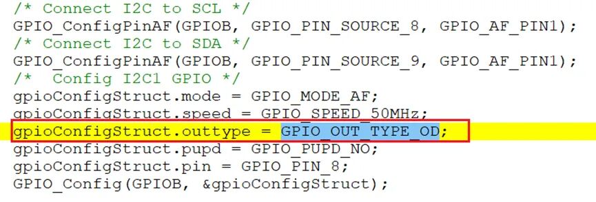

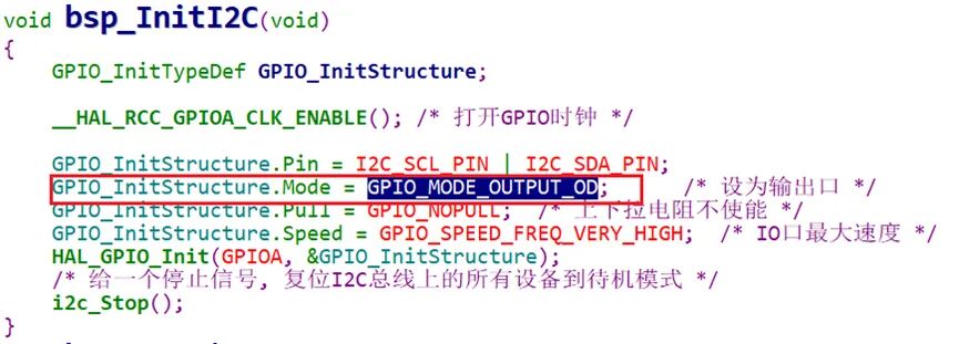
Undoubtedly, all are configured as open-drain outputs.
So, has anyone deeply studied why the I2C pins of an MCU need to be configured as open-drain outputs? Is there any significance to this?
First, let’s discuss what open-drain output means for GPIO!
As we know, among the various GPIO configuration modes of an MCU, one is the open-drain output mode. In this configuration, there is no PMOS transistor, and the drain of the NMOS transistor remains floating.
Therefore, at this time, the state of the GPIO pin connected to the drain is unstable. Generally, an external pull-up resistor (4.7KΩ or 10KΩ) is required on the pin output; when outputting a high level, the NMOS transistor is off, and the pull-up resistor pulls the level high. When outputting a low level, the NMOS transistor conducts, pulling the pin to GND, resulting in a low level, as shown in the figure below:
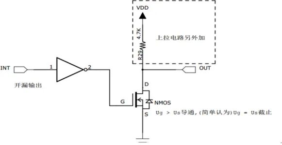
Thus, the high-level signal in open-drain output mode is determined by the external pull-up resistor’s VDD power supply, allowing it to adapt to different voltage signals, such as 3.3V or 5V, without requiring additional level conversion circuits.
In summary, the open-drain mode is very useful due to its flexibility and dependence on external circuits, especially in scenarios where communication lines need to be shared with other devices or level conversion is required.
Next, let’s discuss the reason for configuring I2C pins as open-drain outputs!
We all know that the I2C bus supports a multi-master, multi-slave topology, and this support is closely related to the open-drain output technology. As mentioned earlier, an open-drain circuit can only output a logic 0 and cannot output a logic 1, requiring an external pull-up resistor to pull the level high to the supply voltage. This design allows multiple devices to share these two lines and stabilize the level through the pull-up resistor.
When multiple master devices attempt to send signals simultaneously, the bus will maintain a high level through the pull-up resistor, preventing signal conflicts; only when a master device pulls the corresponding pin low can it control the bus. In simple terms, this ensures that when any master device pulls the bus low, the overall bus is low.
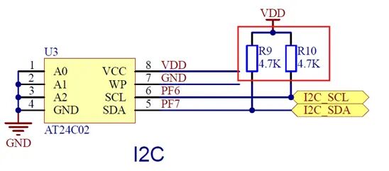
Conversely, if configured as push-pull output mode, it may lead to signal conflicts due to multiple devices attempting to access and control the bus simultaneously, potentially causing device damage due to short circuits.
Additionally, in systems with certain power consumption requirements, this design is also very beneficial. The open-drain structure allows each device to consume almost no current when there is no data communication, only connecting to the bus through the pull-up resistor when communication is needed, thus achieving a reduction in overall system power consumption.
Moreover, the two signal lines designed with an open-drain structure also exhibit good anti-interference performance, allowing the I2C bus to be used in noisy environments.
Considering that in GPIO modes, ordinary output, ordinary input, and analog input are commonly used and familiar, while open-drain mode is relatively less used, the author has briefly introduced the open-drain mode using the I2C bus as an example, hoping that everyone can pay attention to distinguishing and applying it in the future.

END
Author:dffzh
Source: 21ic Electronics Network▍Recommended ReadingWhy is C++ Rarely Used in Microcontroller Development?5 Recommended Lightweight Microcontroller File SystemsCrash! Another Case of Microcontroller Freezing→ Follow for More Updates ←