#RA MCU Testing Guide A new topic has arrived! After saying goodbye to the PWM waveform rhythm, this time we will focus on the indispensable “information bridge” – #Serial Communication. The Renesas Embedded Encyclopedia will guide everyone to explore the configuration and data transmission of serial communication step by step based on the RA-Eco-RA2L1 development board, and see how this classic communication method allows the development board to smoothly “converse” with the outside world.
Open the Guide

01
Unboxing and Project Introduction

A few days ago, I applied for a trial of the #RA2L1 development board. Below is its appearance, with two rows of pins on each side, supporting serial programming and JLink programming.
On the left side, there is a user button, and on the right side is the RST button, with two touch buttons on the top.

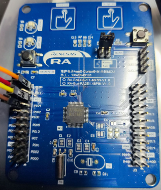
This time, I will use this development board to create a low-power desktop ornament project, which functions as a real-time clock + temperature and humidity meter, using a 0.96-inch OLED screen to display data, with touch buttons to wake it up, and entering standby mode when not awakened.
The expected functionalities of the development board include: I2C, touch buttons, UART, and standby mode.
02
Create Template Project
Developing with Renesas MCUs requires the use of E2 Studio (abbreviated as e2s). I have previously made detailed configuration records while trying out the RA4E2, so I will not elaborate here and will directly start creating the template project.
Scan the QR code below or copy the link to view related information.
E2 Studio Configuration Records
https://bbs.elecfans.com/jishu_2468424_1_1.html

Create New Project
2.1
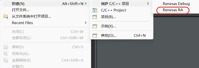
Click New – Renesas C/C++ Project – Renesas RA
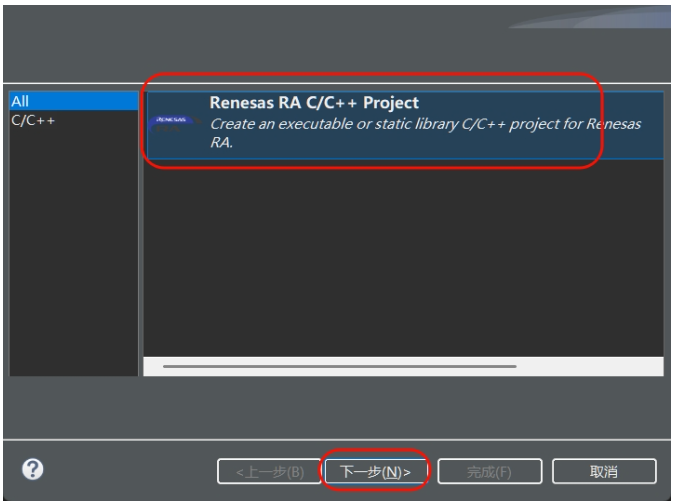
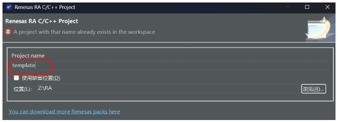
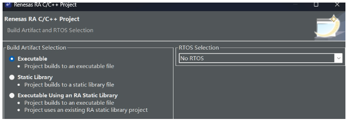
Follow the operations in the image below, where the project name is template, and the main control chip is searched as R7FA2L1AB2DFL, without using FreeRTOS.


Swipe left and right to see more
Set Output HEX File
2.2
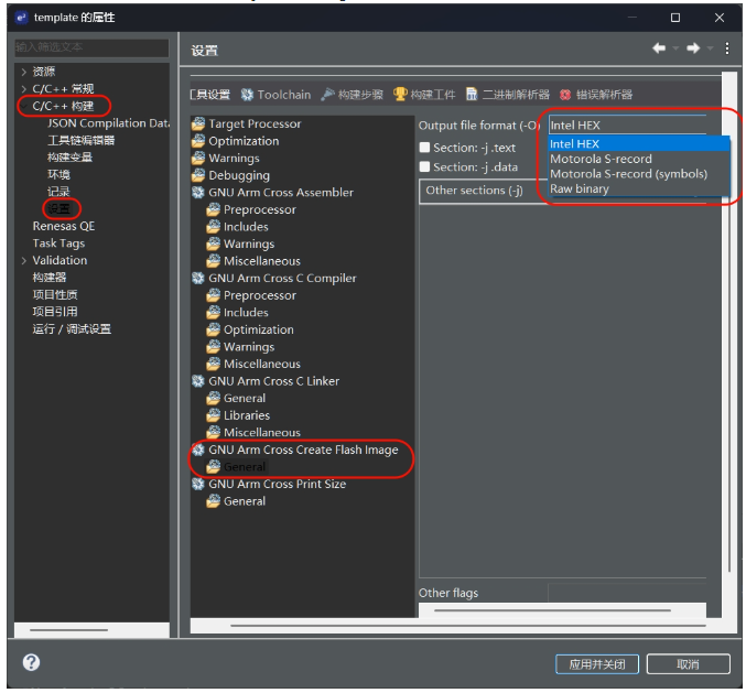
Click on the project in the menu bar – C/C++ Project Settings, find the area shown in the image below, and select Intel HEX.
Click to view the full image
Set Serial Port and printf Redirection
2.3
2.3.1 Set Corresponding Pins for Peripherals
)
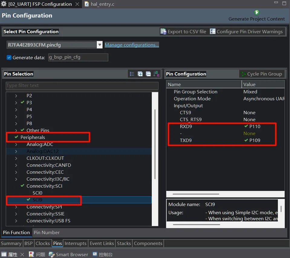
Double-click the configuration.xml file in the project resource manager on the left side of the e2s interface, select Pins – peripherals – Connectivity: SCI – SCI9 in the middle, and set RXD9 to P110 and TXD9 to P109 on the right side.
Click to view the full image
2.3.2 Create and Set Module Properties
)
Click Stacks, New Stack – Connectivity – UART (r_sci_uart)
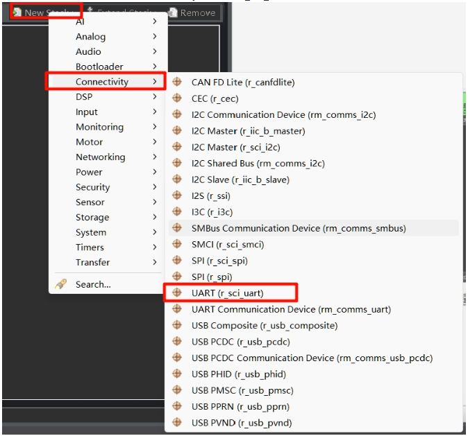
Click to view the full image
Click g_uart0_UART, in the properties dialog, change the name to g_uart9, and set Channel to 9, keeping other property configurations as default.
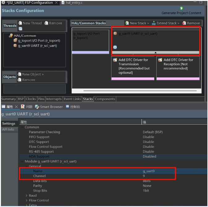
Click to view the full image
Then, in Interrupts – Callback, change it to debug_uart9_callback, which is the serial port interrupt callback function. We will write specific logic in the code later. Every time a character is sent or received via the serial port, the serial port interrupt will be triggered by default, and in the serial port interrupt, the function debug_uart9_callback will be called, where we need to handle different interrupt situations accordingly.
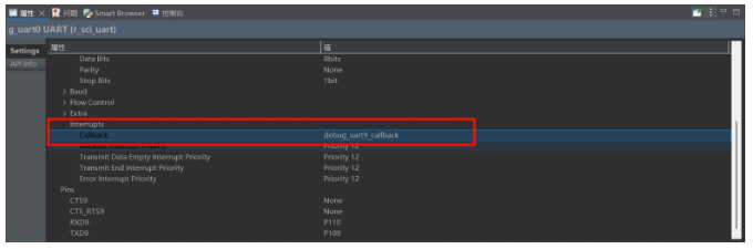
Click to view the full image
2.3.3 Redirect printf Output to Serial Port
)
Although we can directly use the R_SCI_UART_Write function to output strings to the serial port, this function is not as convenient as the printf function in many cases. Therefore, we need to add a piece of code to redirect printf output to UART9.
In the menu bar, click Project – C/C++ Project Settings, check as shown in the image below, and finally apply and close.
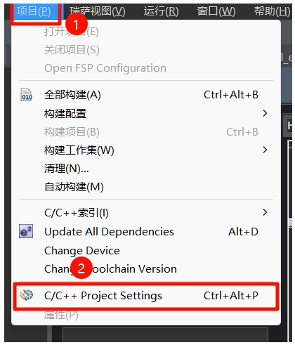
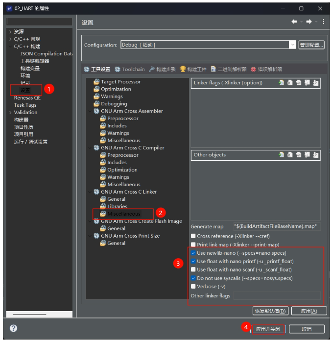
Click to view the full image
Finally, modify the heap size by clicking BSP – Heap Size – change to 0x1000
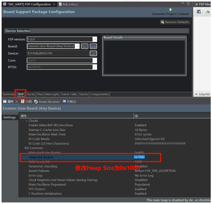
Click to view the full image
Save the configuration file and click Generate Project Content to automatically generate the code for us.
2.3.4 Code Writing
)
In the src folder of the project, create a debug_bsp_uart.h header file and a debug_bsp_uart.c source file.
2.3.4.1 Modify debug_bsp_uart.c
In debug_bsp_uart.c, type the following code, which includes a send completion flag uart_send_complete_flag, the initialization function Debug_UART9_Init for the debug serial port UART9, and the previously configured serial port callback function debug_uart9_callback.
Swipe left and right to view the complete content
#include "debug_bsp_uart.h" /* Send completion flag */ volatile int uart_send_complete_flag = 0; /* Debug serial port UART9 initialization */ void Debug_UART9_Init(void) { fsp_err_t err = FSP_SUCCESS; err = R_SCI_UART_Open(&g_uart9_ctrl, &g_uart9_cfg); assert(FSP_SUCCESS == err); } /* Serial port interrupt callback */ void debug_uart9_callback(uart_callback_args_t * p_args) { switch (p_args->event) { case UART_EVENT_RX_CHAR: { /* Send back the data received from the serial port */ R_SCI_UART_Write(&g_uart9_ctrl, (uint8_t *)&(p_args->data), 1); break; } case UART_EVENT_TX_COMPLETE: { uart_send_complete_flag = 1; break; } default: break; } }Still in the debug_bsp_uart.c file, add the function to redirect printf output.
Swipe left and right to view the complete content
/* Redirect printf output */ #if defined __GNUC__ && !defined __clang__ int _write(int fd, char *pBuffer, int size); // Prevent compilation warning int _write(int fd, char *pBuffer, int size) { (void)fd; R_SCI_UART_Write(&g_uart9_ctrl, (uint8_t *)pBuffer, (uint32_t)size); while (uart_send_complete_flag == 0); uart_send_complete_flag = 0; return size; } #else int fputc(int ch, FILE *f) { (void)f; R_SCI_UART_Write(&g_uart9_ctrl, (uint8_t *)&ch, 1); while (uart_send_complete_flag == 0); uart_send_complete_flag = 0; return ch; } #endif2.3.4.2 Modify debug_bsp_uart.h
In debug_bsp_uart.h, add the following code to declare the function:
Swipe left and right to view the complete content
#include "hal_data.h" #include "stdio.h" void Debug_UART9_Init(void);2.3.4.3 Modify hal_entry.c
At the beginning of the file, add the following code:
Swipe left and right to view the complete content
#include "debug_bsp_uart.h"In the hal_entry function, add the following code:
Swipe left and right to view the complete content
Debug_UART9_Init(); // SCI9 UART debug serial port initializationFinally, compile the project.
Download Test
2.4
2.4.1 Renesas Flash Programmer Software
)
You need to download the Renesas Flash Programmer software, which can be downloaded from the RA ecosystem community website or from the Renesas official website.
Scan the QR code below or copy the link to view related information.
RA Ecosystem Community Website Download Address
https://ramcu.cn/resource/list/?aType=5

Renesas Official Download Address
https://www.renesas.cn/zh/software-tool/renesas-flash-programmer-programming-gui

Here, I will use the serial port download method, with the wiring as shown in the table below.
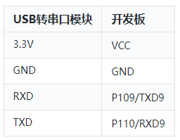
Click to view the full image
2.4.2 Software Configuration
)
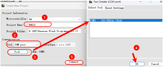
Connect the USB to TTL module to the computer, double-click to open the programming software, and first create a new project.
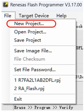
Click to view the full image
Then make some configurations.
Click to view the full image
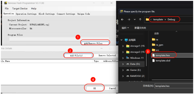
Find the .hex file of the template project.
Click to view the full image
Change the mode selection jumper on the development board to short-circuit the 1st and 3rd interfaces, and press the RST button, then click Start in the software to complete the programming.
2.4.3 Effect
)
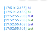
Open the serial port assistant software, set the baud rate to 115200, send any message, and you will see the board sending it back, indicating successful configuration.
Click to view the full image
That concludes the content regarding the RA-Eco-RA2L1 development board’s serial communication. From setting the serial parameters to verifying data transmission, each step has allowed us to better understand the working principle of this “information bridge”. If you have new insights during practical operations or encounter tricky problems, feel free to share and discuss in the comments section. Follow #Renesas Embedded Encyclopedia, and in the next issue of “RA MCU Testing Guide”, there will be more practical features waiting for you to unlock!
The entry for applying for Renesas samples/development boards is as follows, you can scan the QR code or copy the link to the browser to obtain 👇
Application Entry
Renesas samples/development board application entry:
https://jsj.top/f/AgUyYV


Need Technical Support?
If you have any questions while using Renesas MCU/MPU products, you can identify the QR code below or copy the URL to the browser to open, and enter the Renesas Technical Forum to find answers or get online technical support.

https://community-ja.renesas.com/zh/forums-groups/mcu-mpu/
1
END
1
Recommended Reading

RA4M2 Development – Read HS3003 Data and Display on OLED, Serial Print (Part 2)

Worried about OTA failure bricking your device? Boot swap can help you.