“Grounding is considered a solution to many EMI issues. However, when grounding is done improperly, the chosen grounding scheme can become part of the problem. This article illustrates the issue of grounding coupling interference through simple examples.”
01
—
Common Impedance Coupling
According to Ampere’s law (the theoretical cornerstone of EMC grounding concepts – Maxwell’s equations (2)), current flows in a closed loop and then returns to its source. The return current can be split among multiple return paths, with the magnitude of current in each path inversely proportional to the impedance of that path. A common situation in circuit and system design is: multiple circuits share a return current conductor or signal reference structure, and whenever current flows through an impedance, a voltage drop occurs, resulting in common-mode current. This interference coupling mechanism is known as common-mode or common impedance coupling.
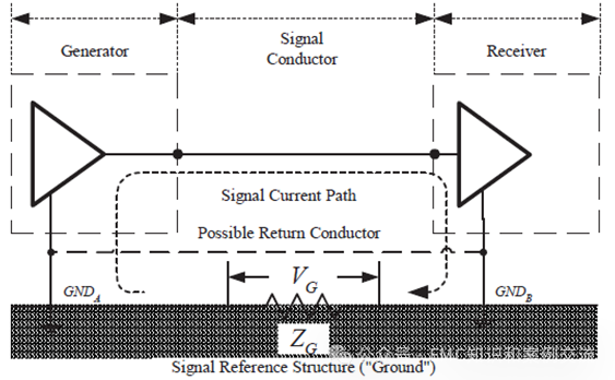
The following diagram illustrates the consequences of non-zero loop impedance. Two single-ended circuits share the same current return path, which has a non-zero impedance ZG (also known as common impedance), which can be resistive or inductive.
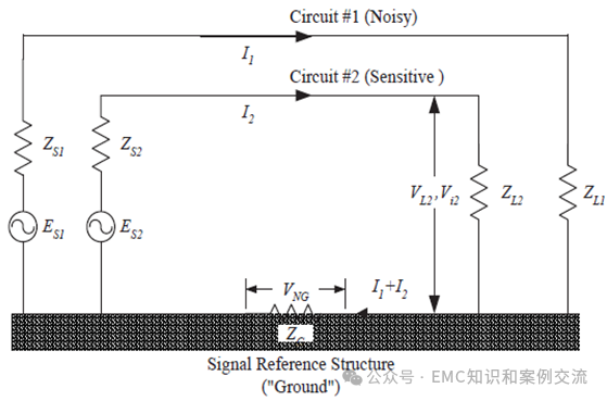
Kirchhoff’s voltage law requires that the sum of all potentials in any closed circuit be zero. Since the current (representing noise) in circuit #1 flows through the signal reference structure shared with circuit #2, a potential difference is introduced between the ground reference connections of circuit #2.
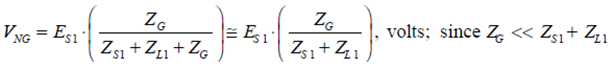
This grounding noise voltage VNG appears as a second voltage source in circuit #2, generating interference voltage Vi2 on the sensitive load of circuit #2:
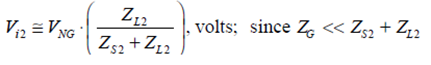
Note: In the above two equations, it is assumed that the impedance of the grounding structure is negligible compared to the source and load impedances in circuits #1 and #2. Combining the above two equations:
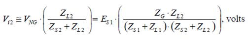
Ultimately, the performance of circuit #2 will be related to the signal-to-noise ratio (SIR) on ZL2:
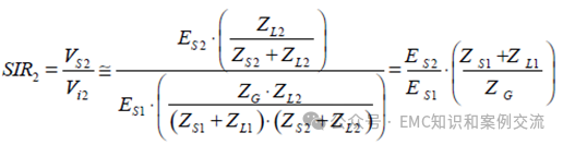
Clearly, SIR is a function of sources ES1 and ES2 and is inversely proportional to the magnitude of the common return path impedance ZG.
02
—
Common Impedance Coupling Cases
Case 1: As shown in the figure below, two single-ended circuits are interconnected by a single wire, with the signal reference and current return path implemented through a grounding reference. Since the reference structure is part of the circuit, the voltage difference VG on the reference structure will introduce noise into the system.
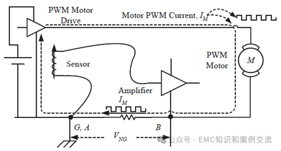
Case 2: The metal frame of a vehicle is often used as the return path for the vehicle battery’s negative terminal. Due to the large transient currents that occur when the vehicle engine starts, the nominal +12 VDC power supply may exhibit transient voltages of up to 100 V. The following diagram illustrates a similar situation where a PWM (Pulse Width Modulation) motor generates interference on sensitive circuits through common loop impedance.
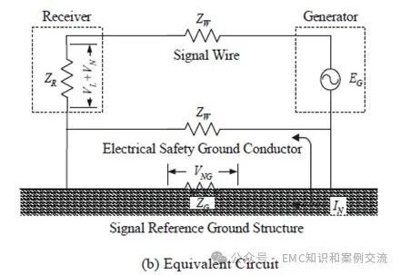
Case 3: The following diagram shows an unbalanced RS-232 digital communication circuit. The RS-232 interface standard does not require the use of dedicated loops, only that grounding is performed at each end of the circuit. One way to achieve this is to connect both the transmitter and receiver circuits to their respective enclosures, which are also connected to ground.
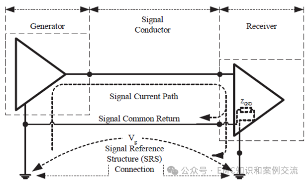
The equivalent circuit is shown in the diagram below. When noise from outside the system generates a voltage drop VNG on the signal reference structure, this voltage drop creates common-mode current on the signal line and signal return path, resulting in interference.
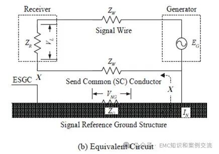
Improving the grounding method of the above circuit, as shown in the diagram below, implements single-ended grounding. Thus, the common-mode current generated by the voltage drop VNG cannot form a loop, thereby not affecting the receiver’s response. Note: This model does not consider parasitic coupling, so this solution is only effective at lower frequencies.
03
—
Factors Leading to Common Impedance Coupling Interference
(1) Non-zero impedance characteristics of the common return path;
(2) Multiple systems sharing a common return path;
(3) Circuits exhibiting low noise tolerance due to their unbalanced characteristics.
———————————————
For more content, please follow our public account.