I have been writing RTL for over a decade and have encountered various engineering coding standards, constraints, and suggestions. Therefore, I am summarizing my experiences at this stage. The Verilog/SV coding suggestions and some engineering requirements mentioned and discussed in this series are based on what I have encountered and understood during my work process. They are not universal coding standards and do not represent my personal endorsement of these norms; they are merely a discussion of the reasons and pros and cons of these suggestions.
For the first seven articles in this series, please refer to:
- Why it is required not to use always in RTL
- Why to avoid the misuse of macro definitions in RTL
- Why to avoid using tasks in RTL
- Why to prioritize using reset-free registers in design
- Why to avoid introducing delays with #delay in RTL
- Why to avoid -y and -v indexing in self-developed code file lists
- Why to avoid using casez/casex in RTL
In Verilog syntax, there are two common for loop structures: the regular for loop and the generate-for loop. SystemVerilog also extends the for syntax. In my previous company, the use of generate-for was prohibited. Frankly, this is the coding constraint I understand the least and disagree with the most. I privately feel that it is overly cautious and counterproductive. I have also asked why this rule was added, and the responses I received generally included the following considerations:
1. The impact of implicit loop-generated logic on the backend. This reason seems to be a catch-all for any constraint. Simply put, the logic generated by the generate-for syntax is implicitly expanded in the code, which may make locating and modifying the target logic more difficult. It can cause some confusion in determining and optimizing timing paths, as well as in finding specific gate cells during ECO. I believe that as long as the label names are clearly written, this should not pose a problem (of course, I have not done ECO, so I have no authority to speak on this). Even if there are issues, they should be addressed by EDA tools.
2. Differences in tool support. This is also a vague reason; many coding rules have been dismissed with this justification. There is concern that some EDA tools may not fully support the generate syntax, especially in older versions or specific toolchains, which could lead to synthesis or simulation errors. However, I have not encountered this issue so far, so I remain skeptical. A friend in the comments section provided a VHDL example: “The compiler may indeed have issues; previously, when using Zhongke Y*wei’s *linx, it could not correctly recognize generate-for in VHDL, and I had to copy the code several times.”
3. Increased complexity in verification and coverage. This includes decreased simulation performance, increased difficulty in simulation localization, more complex coverage collection (especially in cases of instantiation with loops and conditions), and increased complexity in aligning and localizing pre- and post-simulation. I personally think this point has some validity.
4. Increased difficulty in ECO. This has been mentioned many times, leading to my ongoing anxiety about lacking ECO experience. Some ECO tools (but which ones?) may have limited support for the generate syntax, especially when dealing with complex conditional generation or nested generation. Additionally, during the ECO phase, synthesis and layout tools need to reprocess the modified logic. If the logic generated by the generate syntax is handled inconsistently during synthesis and layout, it may lead to ECO failures or introduce new problems.
The main reasons discussed are these four. However, even if everyone follows this rule, there are still many situations where generate-for is irreplaceable, such as parameterized instantiation of several modules or logic. This has led to other issues and tools; I have even written an auto_unfold script in Python to expand for loops, which may not be very useful, but it is quite handy for generating massive amounts of loop text.
Since I personally do not agree with this coding suggestion and do not follow it much, I will not elaborate further. Instead, let’s talk about regular for loops. I had previously taken notes on some pitfalls of for loops (non-generate-for) a long time ago, and in this article, I will reproduce some of the code behaviors that I had previously warned against. This is essentially a rewrite of that article. The verification environment in this article is generated by auto_testbench, and the compiler used is VCS (the one used in the previous article was ModelSim).
Overall, the main pitfalls of for loops are two: non-blocking assignments and else branches. Once a for loop is coupled with these two situations, one needs to be especially vigilant. Let’s directly look at a few typical negative examples/error demonstrations. The code comes from notes I took when I asked experts questions; no one in actual projects would write such outrageous code. Therefore, the original purpose of the code is not to delve too deeply but to focus on the simulation behavior.
The first piece of code is somewhat foolishly written, but to showcase the syntax characteristics, let’s take a look:
logic [DATA_WD -1:0] sign; logic [$clog2(DATA_WD) -1:0] cnt; always @(posedge clk) begin integer i; for(i=0; i < DATA_WD; i=i+1) begin cnt <= cnt + sign[i]; end endThe meaning is to calculate how many bits in sign are 1. Here, non-blocking assignment is incorrectly used. Thus, the code behavior becomes:

In other words, this piece of code is equivalent to:
always @(posedge clk) begin cnt <= cnt + in_vld[0]; cnt <= cnt + in_vld[1]; ... cnt <= cnt + in_vld[PORT_NUM-1]; endBecause it is a non-blocking assignment, the order of execution does not have a relationship, and the final result largely depends on the compiler’s mood (I am not sure about this; previously, I saw that the execution order in the protocol timeslot mechanism was written as “E = any event from region,” so I have always understood that there is no determined order). VCS should execute cnt <= cnt + in_vld[PORT_NUM-1]; Regardless, this behavior deviates from our expectations (though it is a reasonable simulation behavior).
The second piece of code is intended to avoid the appearance of latches. Previously, everyone said that if there is an if in always@*, there should be an else, so I wrote an else. However, I must emphasize that this code does not need to be written this way; it is quite silly and is merely to demonstrate simulation behavior:
logic [DATA_WD -1:0] sign; logic flag; always @* begin integer m,n; for(n=0; n < DATA_WD; n=n+1) begin if(sign[n]) flag = 1; else flag = 0; end endThis writing does not even require simulation waveforms; it will inevitably only check the last bit of sign. This code leads to the third piece of code. The intention of this code is to obtain data from the highest priority port, where in_vld[PORT_NUM-1] has the highest priority and in_vld[0] has the lowest. Therefore, in the for loop, I check the value of in_vld[i] from low to high; if it is 1, data0 is taken; if it is 0, data0 remains unchanged, and I directly wrote it in the sequential unit:
logic [DATA_WD -1:0] data0, data1; logic [DATA_WD*PORT_NUM -1:0] in_data; logic [PORT_NUM -1:0] in_vld; always @(posedge clk) begin integer i; for(i=0; i < PORT_NUM; i=i+1) begin if(in_vld[i]) data0 <= in_data[DATA_WD*i +:DATA_WD]; else data0 <= data0; end endSo what is this code equivalent to? It is equivalent to:
always @(posedge clk) begin if(in_vld[PORT_NUM-1]) data <= in_data[DATA_WD*(PORT_NUM-1) +:DATA_WD]; else data <= data; endIndeed, it will only check the highest bit of in_vld and ignore other bits. Looking at the waveform:
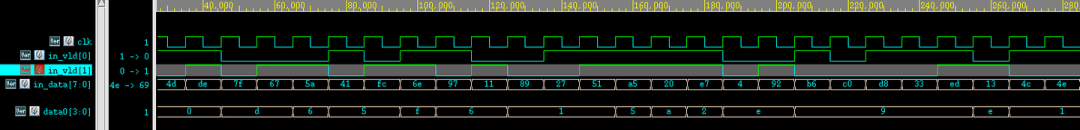
Only when in_vld[1] is high will data0 change; in_vld[0] is completely ignored. Therefore, this requirement is best written in a blocking assignment for loop. If it must remain non-blocking, then just remove the else:
always @(posedge clk) begin integer i; for(i=0; i < PORT_NUM; i=i+1) begin if(in_vld[i]) data1 <= in_data[DATA_WD*i +:DATA_WD]; end endThen the behavior will meet expectations:

| [Chip Design] SoC 101 (1): Introduction |
| [Chip Design] A Discussion on FIFO (0): Starting from Ubiquitous FIFO |
| [Chip Design] Computer Architecture (1): Virtual Memory |
|
[Chip Design] In-Depth Understanding of AMBA Bus (0): Introduction |
| [Chip Design] Introduction to Handshake Protocols and Timing Explanation |
| [Chip Design] Small Matters of Reset – Reset Debouncing |
| [Chip Design] Quick Start to Digital Chip Design (1): Introduction |
| [Chip Verification] UVM Source Code Plan (0): Self-Assessment Before Determining to Read Source Code |
| [Chip Design] Musings on Asynchronous Circuits (1): What Exactly is an Asynchronous Circuit |
| [Chip Design] From RTL to GDS (1): Introduction |
| [Chip Design] Design of Testable and Observable State Registers in Systems |
| [Chip Verification] sva_assertion: 15 Assertion Exercises to Help Ascend |
| [Chip Verification] Possibly the Pinnacle of RTL Directed Verification |
| [Chip Verification] Propagation of X State Behavior in RTL Simulation – Starting from xprop |
| [Chip Verification] The First SystemVerilog Verification Environment for Young People: Full Project and Analysis |
| [Chip Design] An Exploration of the Essence of Signed and Unsigned Numbers in Verilog |
| [Chip Design] On the Disappearance of Always Syntax in RTL |
| [Chip Design] Code is Comment, Comment is Code |
| [Chip Design] You Can’t Expect Too Much from a 700-Line RISC Processor |
| After joining the chip development department, what should we do besides slacking off every day? |
| How to calculate the system’s outstanding and burst length? |
| Daily Chip Work: The Event of Misaligned Keywords that Drives Perfectionists Crazy |
| In a familiar society, a group of outsiders without social value |