Another colleague has encountered a problem. After receiving the prototype circuit board, they found that the Ethernet could not be pinged at all. While helping to check the circuit, I discovered a detail that 99% of people overlook: 🧐 The most feared thing when designing a PCB is this “Schrödinger’s Pin” — the center tap of the Ethernet transformer! Here’s a picture: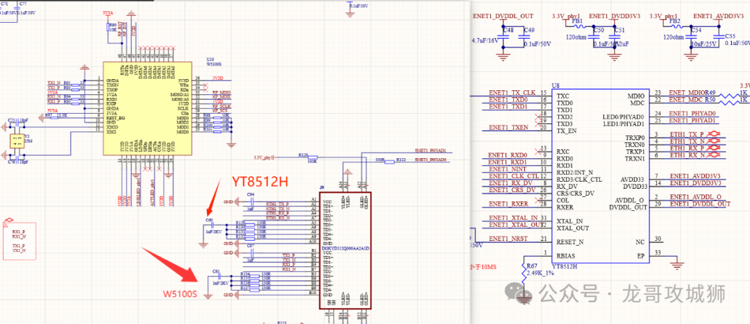 That’s right, there are two Ethernet PHYs here: W5100S and YT8512H. Currently, YT8512H is communicating normally, while W5100S cannot be pinged.First, the answer: When connecting the W5100S to an external RJ45, the center tap of the transformer must be connected to power!👉Core Issue: The handling of the Ethernet differential signals (TX+/TX-, RX+/RX-) through the transformer (MagJack or separate transformer) directly affects the signal quality, common-mode noise suppression, and EMI! If connected incorrectly, it can lead to packet loss and reconnections, or in severe cases, complete communication failure! 😱
🔍 Core Answer: It depends! Mainly on the PHY chip model!
That’s right, it’s not fixed! It mainly depends on your Ethernet PHY chip. How to determine? Let me teach you two tricks:
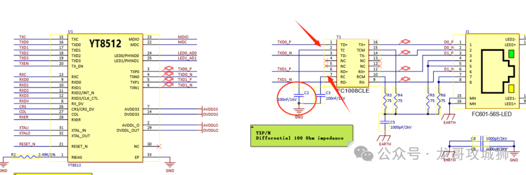
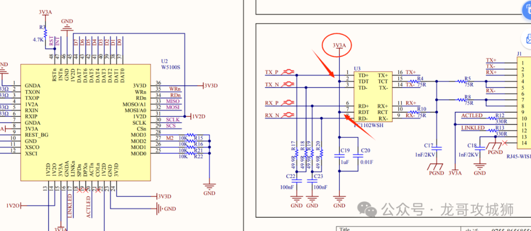
1. Check the official “reference answer” — “reference design”! This is the most reliable method! Open the schematic of the official demo board for your PHY chip and copy the work of the experts! 📖 (As shown below: W5100S & YT8512 official reference design)
2. Check the chip manual’s “explicit provisions” — “Center Tap” Search for “Center Tap” or “CT” in the PHY chip’s datasheet. There will be clear instructions:
-
If it requires “bias to 2.5V” or “connect to VCC” ➡️ Then the center tap must be connected to power through a resistor/inductor (usually 3.3V or 2.5V).
-
If it requires “AC ground” or “ground through a capacitor” ➡️ Then, just like the reference design, use two capacitors to ground it!
⚡️ Soul-Searching Question: How should my board be connected?
The answer is: Check the datasheet! Check the datasheet! Check the datasheet! (Important things are said three times!)
What pitfalls have you encountered while designing boards? Let’s discuss in the comments! 
 From microcontrollers to ARMLlinx, from hardware design to PCB layout, from RFID to system solution design, from IoT to QT, rejecting routines, feel free to scan and follow me. Whether you are a beginner or an industry elite, let’s brainstorm and speak freely!