
Hello everyone, I am “Uncle”. In this article, we will explore how to achieve automation upgrades in factories using Siemens PLCs (Programmable Logic Controllers). You might think, “PLC sounds complicated, isn’t it just about controlling motor switches?” In fact, the functionality of PLCs goes far beyond that; they are widely used in modern industry to not only enhance production efficiency but also help enterprises achieve intelligent management.
Today, we will start from scratch to understand the basic principles, practical applications, and some common problem-solving strategies related to Siemens PLCs. Whether you are new to automation or an experienced technical enthusiast, you will surely gain a lot of insights after reading this article.
The working principle of a PLC is actually quite simple. Just like a remote control for home appliances, a PLC receives external signals through input devices (such as sensors) and then outputs control signals (such as turning on a motor) according to a predetermined program. The PLC’s “inputs” are typically sensors, buttons, etc., while the “outputs” control devices like motors and lights.
Common components of Siemens PLCs include the CPU (Central Processing Unit), input/output modules (I/O), power supply modules, etc. By programming, the PLC can determine whether to trigger an output signal based on input signals, thus controlling the state of the devices. For example, suppose you have installed a temperature sensor on the production line; when the temperature reaches a certain threshold, the PLC can control the fan to start through the output signal.
In a PLC control system, the input and output ports are crucial. The input ports receive signals from external sensors, while the output ports control the actions of devices through actuators (such as motors, cylinders, etc.). Siemens PLCs have various types of I/O modules to meet different application needs.
Let’s look at a simple circuit diagram showing how to connect the input and output ports:
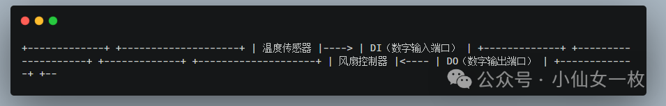
——————+
In this wiring diagram, the temperature sensor transmits data to the PLC through the digital input port (DI), while the PLC controls the fan’s switch through the digital output port (DO).
PLC programming usually adopts Ladder Diagram, which is very intuitive and resembles an electrical schematic. Each “rung” of the ladder diagram represents a logical control process. Below is a simple ladder diagram used to control the fan’s switch.
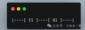
I1: indicates the input port (e.g., sensor input signal).
Q1: indicates the output port (e.g., the signal to start the fan).
When I1 (sensor) detects that the temperature exceeds the set value, the PLC outputs a signal to Q1 to start the fan; otherwise, it will turn off the fan.
Let’s look at a specific case to see how PLCs achieve automation control in actual production environments:
Suppose you have an automated production line that includes multiple conveyors and sensors. By controlling these sensors and conveyors through PLCs, the production line can operate automatically. For example:
Sensor S1: detects that materials have reached a specified position, and the PLC receives the signal through the digital input port.
Conveyor T1: the PLC sends a signal through the digital output port to start the conveyor, and the materials begin to move.
Sensor S2: When the materials reach the next station, the PLC receives the S2 signal again, stops the conveyor, and starts the next operation.
In this way, the PLC can automatically control various aspects of the production line, significantly improving production efficiency and reducing manual intervention.
In practice, we often encounter some issues. Here are a few common situations along with their solutions.
Solution: Check if the wiring of the input port is secure. If the signal is unstable, it may be due to loose connections or sensor faults. You can use anti-interference circuits to ensure stable signal transmission.
Solution: Confirm that the voltage of the sensor matches that of the PLC. If the voltages are incompatible, a signal converter may be needed. Also, check the operational status of the sensor to ensure it is functioning properly.
Solution: Check if the PLC’s output port is correctly connected to external devices and confirm that external devices (such as motors, valves, etc.) can receive control signals. If there is no response from the output port, check if the program and hardware connections are correct.
During debugging, be sure to avoid incorrect wiring. Ensure that the signal types and voltage ranges of each input and output port are correctly matched.
For controlling high-voltage electrical devices, ensure proper electrical safety measures are in place to prevent electric shock accidents.
During debugging, always use appropriate tools for testing; multimeters, oscilloscopes, and other tools can help you better diagnose issues.
Start with simple projects, such as motor start-stop control. Gradually familiarize yourself with PLC programming, wiring, and debugging techniques.
During debugging, use the simulation function to test programs in advance to avoid hardware damage.
For common applications like conveyor control and temperature control, you can adapt the program to different scenarios by modifying it, thereby enhancing your programming skills and debugging experience.
This concludes our discussion on the basics of Siemens PLC and automation control, along with some practical experiences. PLCs are essential tools in industrial automation, helping enterprises improve efficiency, reduce costs, and enhance workplace safety. If you have any questions or wish to learn more, feel free to leave a comment for discussion.