1. Siemens PLC1200 Communication Settings
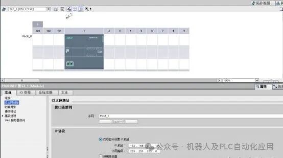
Set the Ethernet address of the PLC, while noting the rack number and slot number, which will be used in the subsequent VisionMaster setup.
 Set the PLC connection mechanism, check the option {Allow PUT/GET communication access from remote objects}.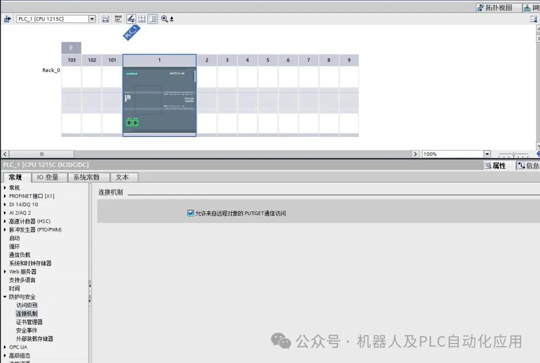
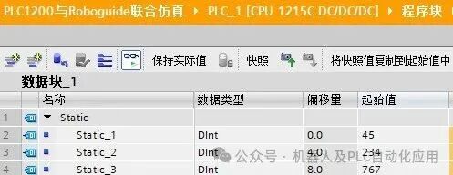
Create a DB block to store the variables for communication, and create 4 double integer variables Dlnt, 32bit.
2. VisionMaster Communication Settings
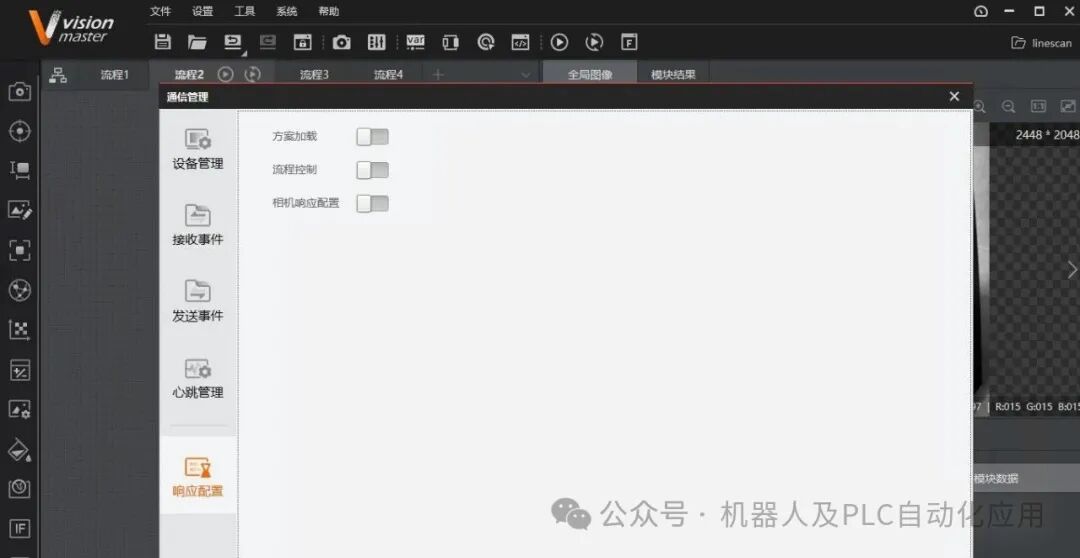
Run the VisionMaster software and open the communication management.
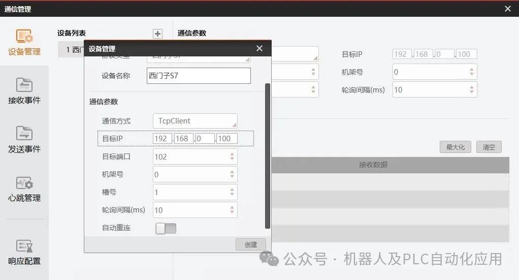
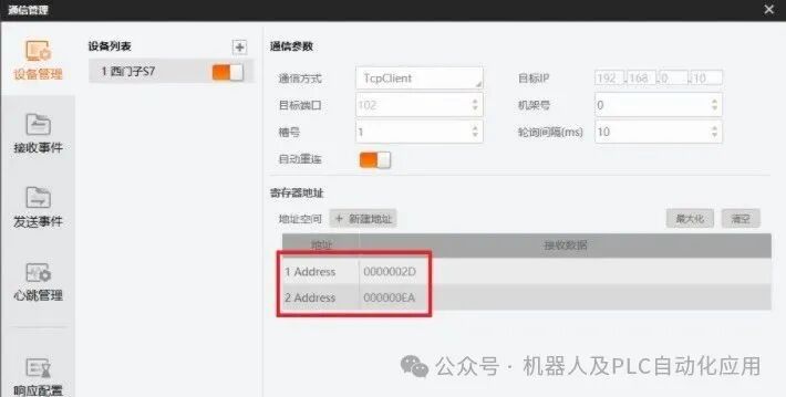
 Click on Device Management, add a device, select Siemens S7, communication method TcpClient, and set the target IP to the previously edited IP address. The communication port for Siemens PLC is 102, and the rack number and slot number were mentioned in the first step (Rack number: 0, Slot number: 1).
 Next, the newly created register address and communication parameters should be consistent with the parameters of DB2 block in Siemens TIA.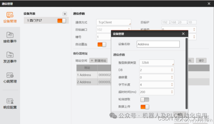
3. Communication Debugging
After creating the four variables, click {Data Synchronization}, the values of the first two variables in the PLC’s DB block will be transferred to the 4 registers in VisionMaster.
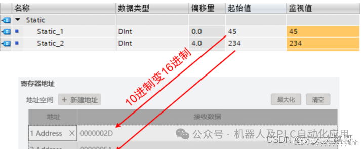
 Click {Send Data}, a send test interface will pop up, enter the address and data type, and input the data. The first variable value in the PLC1200 online monitoring DB block is xxx, indicating that the communication test is successful.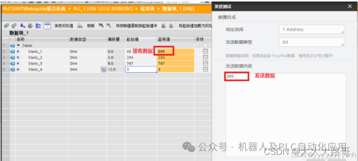
4. External PLC Triggering Multi-Process Operation in VisionMaster
1. Communication Management – Device Management
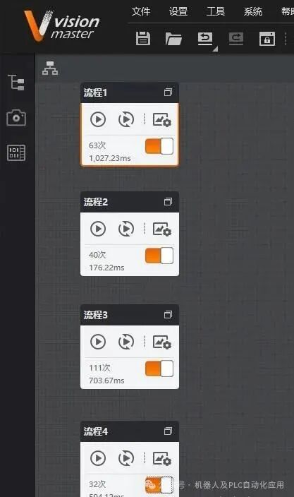
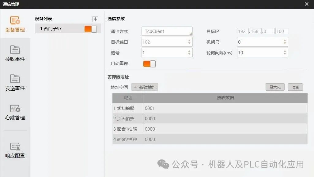
Next, use the register {Address1} as the trigger variable for the external PLC. When Address1=0001, execute Process 1.
2. Communication Management – Receive Events
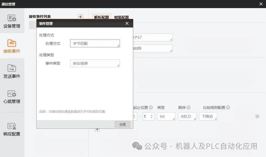
Hover over {Receive Events}, click “+” to add a receive event, a {Event Management} interface will pop up, select the processing method as “Byte Matching” and the event type as “Protocol Assembly”, then click Create.
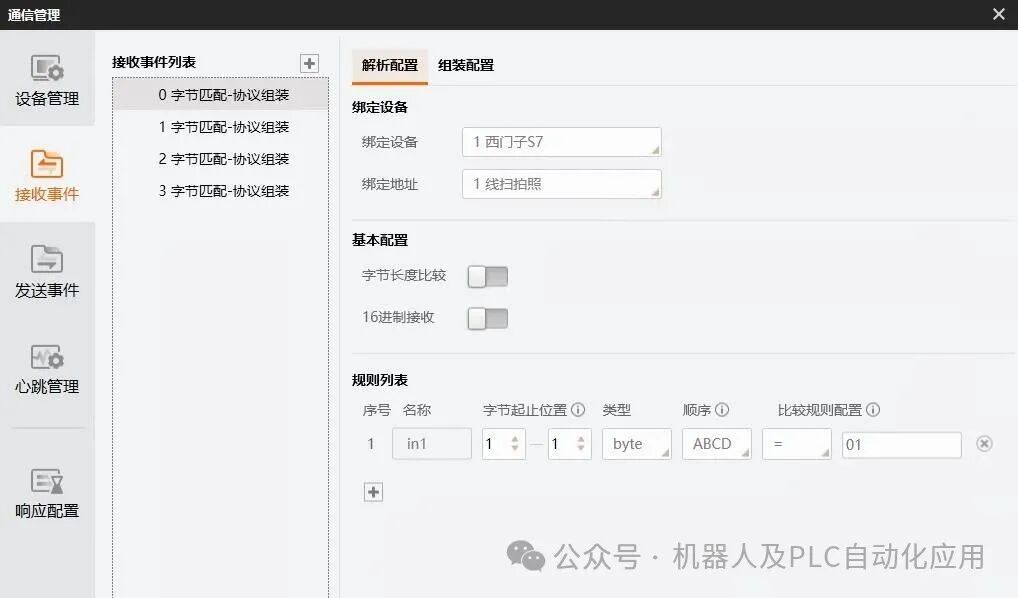
We have already added the device and address, now we bind the device and bind the address, selecting the previously edited data.Address1=0001, 16 bits, 2 bytes, from left to right the first byte is 00, the second byte is 01, so when comparing characters, just use the first byte 01.
 Of course, multiple characters can also be compared, as long as the number of characters being compared is the same and the starting address is the same.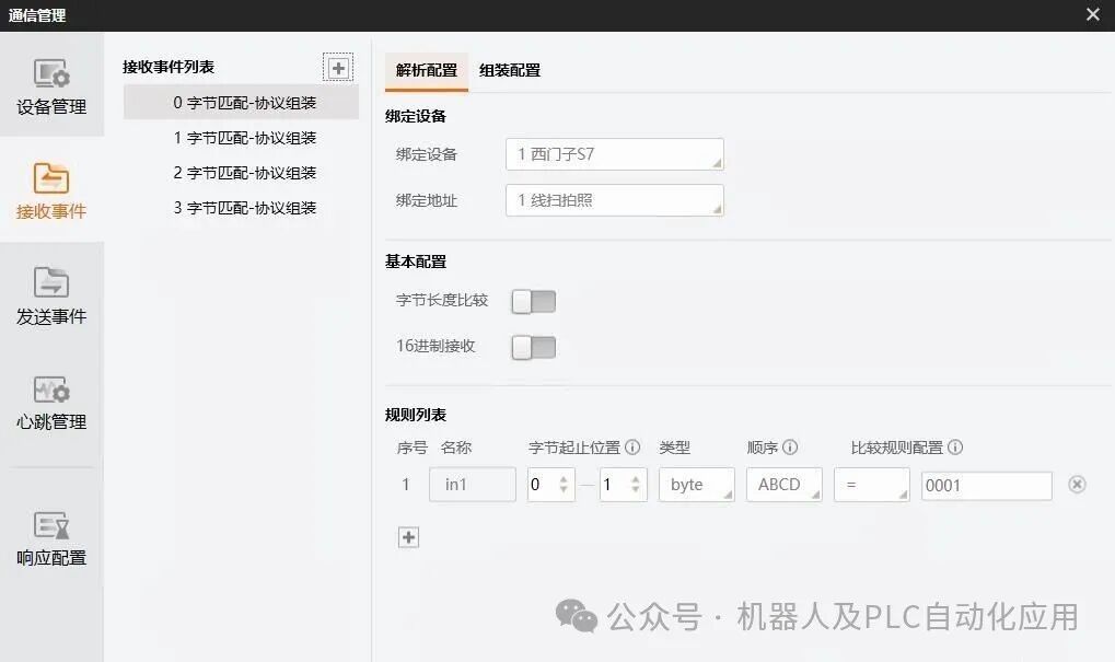
3. Global Trigger
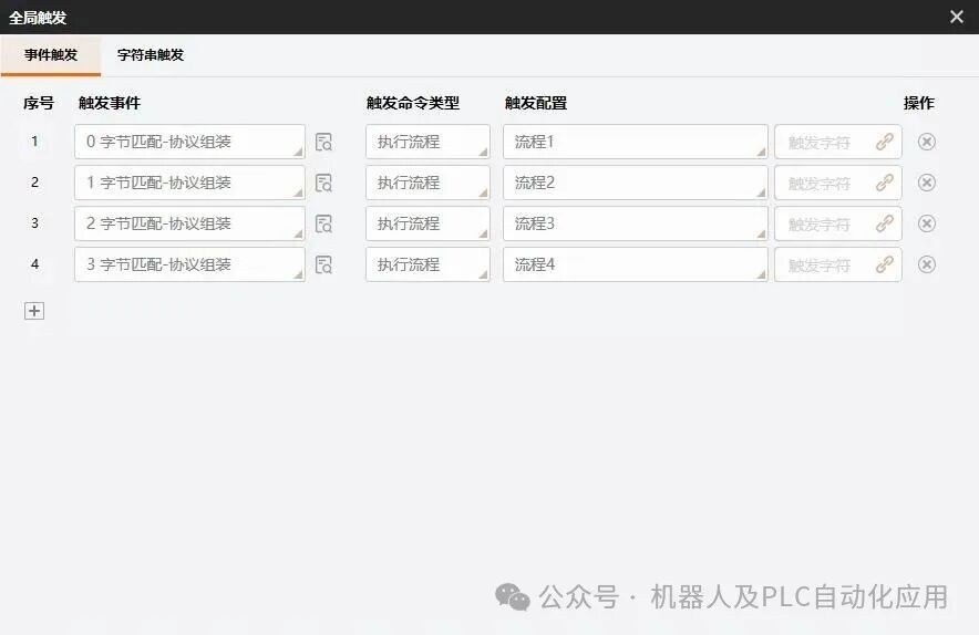
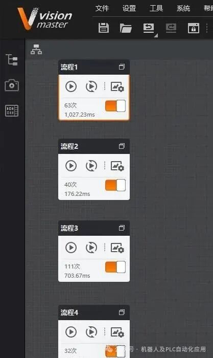
Next, set the global trigger, click {Global Trigger}, the trigger event bit is the {0 Byte Matching – Protocol Assembly} created in the receive event; select the trigger command type as {Execute Process}, and select the trigger configuration as {Process 1}, at this point Process 1 starts running.
4. A Trigger Command Executes a Process Once
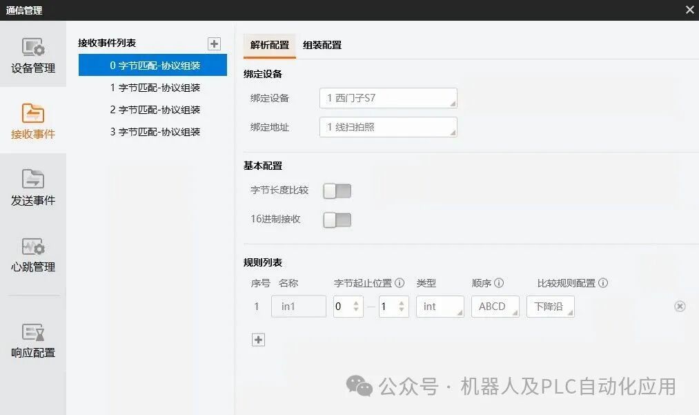
The above settings will cause the process to run multiple times continuously, but sometimes we need a trigger command to execute the process only once. We need to set this in the parsing configuration, selecting the type as {int} and the comparison rule as {falling edge}.
Comparison rule: Rising edge: changes from other values to 1; Falling edge: changes from 1 to other values, the above applies to int type data.