Click the above  “Easy Learning Electronics” to easily learn electronic knowledge by following us.
Analog variable frequency filters require the use of variable passive components. The steeper the filter slope, the more variable passive components are needed. Many of these components are potentiometers. For example, a low-pass Butterworth filter with an 18dB/8 octave slope requires a potentiometer with three groups. If we also need to retune both the low-pass and high-pass filters simultaneously, the required number of potentiometer resistance taps will double.
This is also the case when we need to retune multiple identical filters simultaneously. These multi-group potentiometers are very expensive and hard to find. Another issue is their group error, which can be about 3dB in practical use. The size of these potentiometers is usually large. Additionally, wear on the potentiometers can produce “zipper” noise.
Another way to implement these filters is to use active components instead of variable passive components. The most suitable component is the voltage-controlled amplifier—VCA. The variable in the VCA circuit is the gain, which changes according to an external control voltage.
The most common VCA unit is designed as a current-in/current-out device, and it exhibits an exponential response at the voltage-sensitive control port.
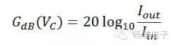
The gain of the VCA unit is:
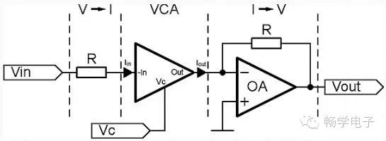
Figure 1: Typical VGA circuit.
The input voltage Vin is converted to input current Iin through resistor R. VC is the control voltage for modulating gain. The process of controlling gain in the VCA is: converting the input current signal into a bipolar logarithmic voltage, adding it to the DC control voltage VC, and then converting the summed voltage back to current through a logarithmic circuit. The output current Iout of the VCA is converted to voltage Vout through an op-amp based I-V converter, as shown in Figure 1, where the conversion ratio depends on the feedback resistor connected between the output and the inverting input. The signal path through the VCA and output op-amp is in-phase because the VCA is inverting. If the VC pin is grounded, the output current will equal the input current.
If using a decibel scale (Figure 2), the relationship between control voltage and gain is linear:
Each VCA manufacturer provides different response scales. For example, SSM2164 is -33mV/dB, SSM2018 is -30mV/dB, and THAT2180 is ±6.1mV/dB.
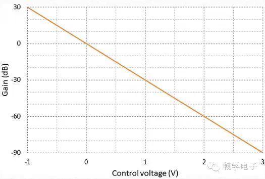
Figure 2: Gain vs. Control Voltage Relationship for SSM2164.
Let’s start with an example of a first-order low-pass filter:
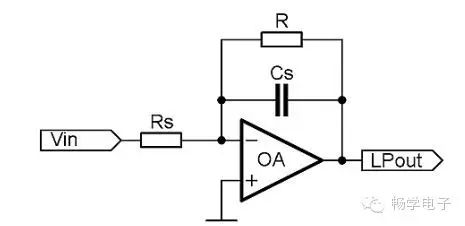
Figure 3: Op-Amp Based Single-Pole Low-Pass Filter.
The cutoff frequency of this filter is:
The cutoff frequency of this type of filter is often changed by adjusting the resistor RS. If a voltage-controlled amplifier is used in the preceding circuit, the schematic of the filter will change as follows:
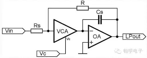
Figure 4: VCA Based Single-Pole Low-Pass Filter.
This is a typical first-order low-pass filter, but the cutoff frequency depends on the VCA gain. If the gain is 1, the VCA behaves like a short circuit, and the cutoff frequency depends only on the values of Rs and Cs. If the gain is greater than 1, the VCA acts as a negative resistance (increasing the cutoff frequency). If the gain is less than 1, the VCA acts as a resistance (decreasing the cutoff frequency).
After using the VCA, the cutoff frequency of the filter equals:
, where G represents the VCA gain.
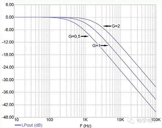
Figure 5: Frequency Response of the Filter in Figure 4.
If we want to control both the low-pass and high-pass filters simultaneously with the VCA, it is best to use a state-variable filter (Figure 6). The state-variable filter consists of integrators (OA2) and summing/differencing amplifiers (OA1). Signals from all stages of the circuit are used for feedback. These filters have lower sensitivity to component values and are easy to design.
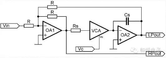
Figure 6: VCA Based Single-Pole State-Variable Filter.
When VC is 0, the cutoff frequency is determined by the circuit RSCS. As VC increases, the cutoff frequency decreases with a slope determined by the VCA gain constant.
If the VCA gain in dB is non-zero, the transfer angular frequency fC2 is:
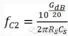
For a known gain control constant GC, the transfer frequency is:
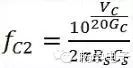
Where VC represents the VCA control voltage.
For example, if the VCA has a gain control constant of -50mV/dB, and VC equals 1V, then the cutoff frequency will be 1/10 of the cutoff frequency determined by RSCS.
The following formula expresses the control voltage needed to change the cutoff frequency from fC to the target value fC2, where fC is determined by RS and CS.
From the above formula, it can be seen that VC controls the cutoff frequency with an exponential response characteristic.
For high-slope filters, we must increase the order of the filter. Figure 7 shows a dual-channel fourth-order Linkwitz-Riley state-variable filter controlled by a potentiometer or digital-to-analog converter (DAC). In one channel, there are 4 integrators plus a summing/differencing stage circuit, and feedback from all 4 integrators returns to the summing/differencing stage circuit. IC3 acts as a buffer, driving the control ports of all 8 VCAs. The voltage from the potentiometer or DAC is applied to the inverting input. This voltage is then attenuated or amplified by the gain of IC3, which is determined by resistors R13 and R14.
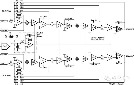
Figure 7: Dual-Channel High-Slope Variable Frequency Filter.
Figure 8 shows the frequency response of the filter shown in Figure 7, where the low-pass output and high-pass output are also plotted. The center gain is 0dB, and the angular frequency is set close to 1kHz by RS and CS. If the gain doubles, the cutoff frequency will also double (approximately 2kHz). Similarly, if the gain is halved, the cutoff frequency will also be halved (approximately 500Hz).
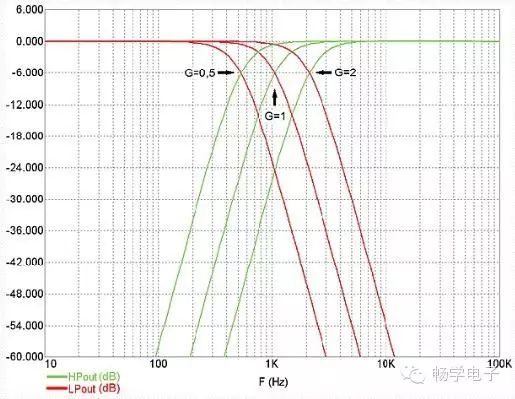
Figure 8: Frequency Response of the Fourth-Order Variable LR Filter at Three Different VCA Gains.
Because precision E192 resistors, matched capacitors, and high-speed operational amplifiers were used in the final design, the measured characteristic data is very accurate.
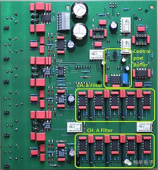
Figure 9: VCA Controlled Filter as Part of a More Complex System.
> > > > > > > > > > > > > > > > > > > > > > > > > > > > > > > > > > > > > > > > > > > > > > > > > > > > > >
==> Visit www.eeskill.com to learn more!