PCB Network News
What is Freeduino?
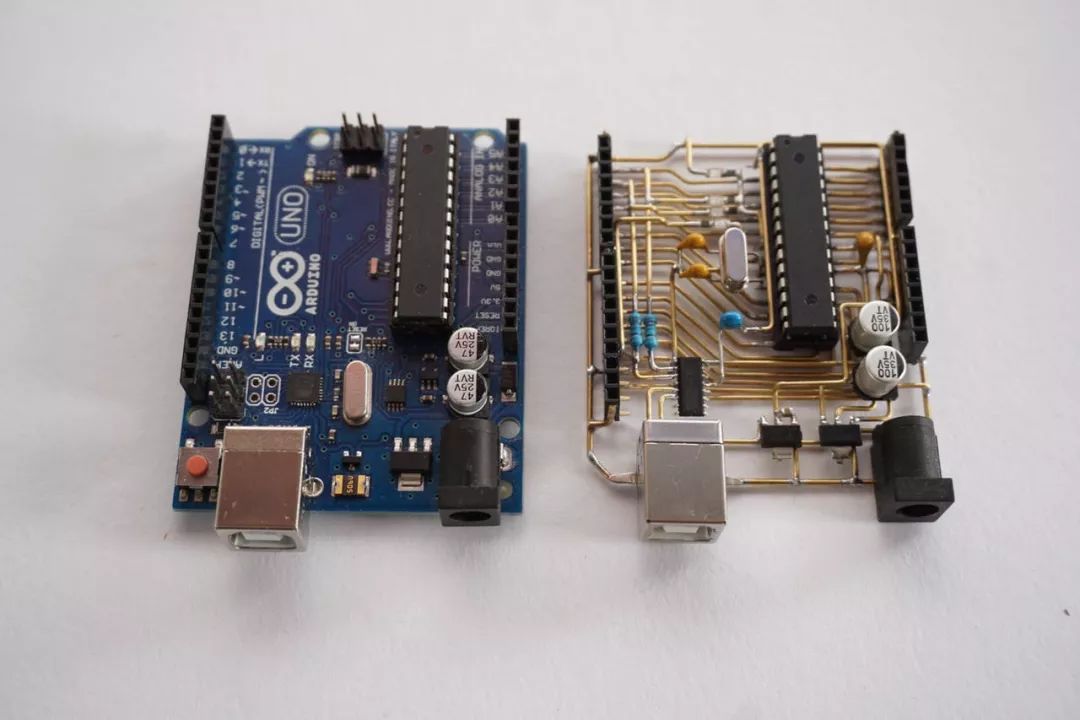
It is an Arduino UNO board without any circuit board.
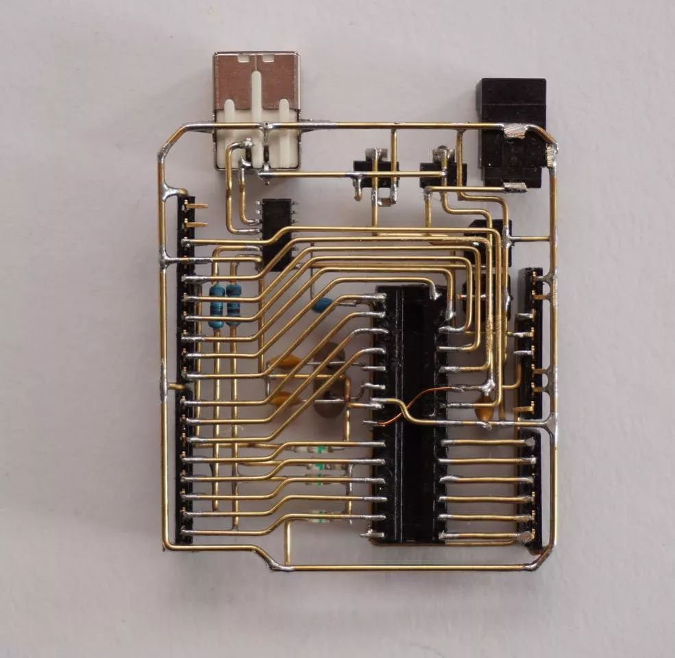
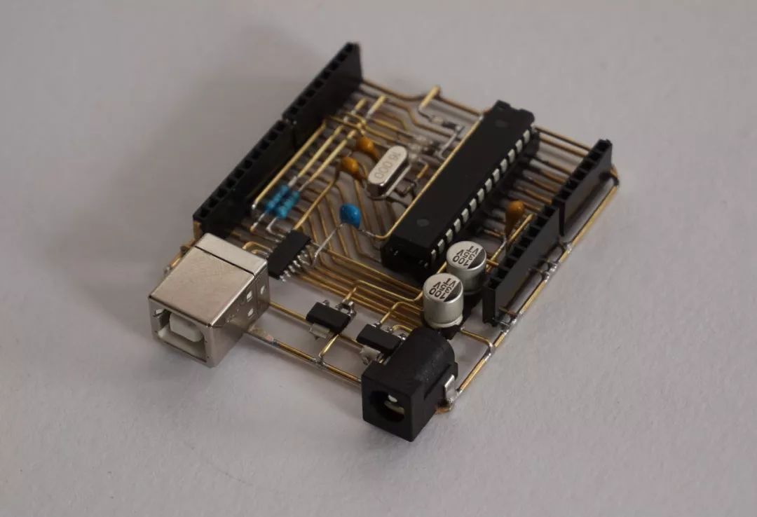
It interconnects components using a technique called freeform, utilizing wires or copper instead of a circuit board. It looks minimalistic and beautiful!Freeduino is a great example of freeform electronic art, easily comparable to the well-known Arduino UNO.
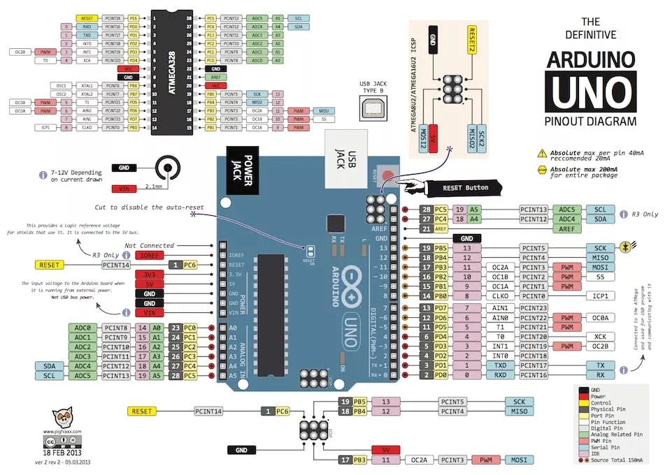
Understanding Arduino UNO Circuit
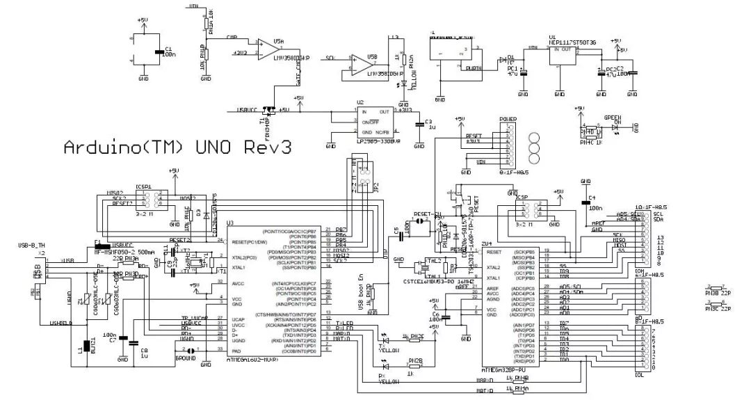
Before starting to solder, it’s important to understand the function of each part of the Arduino UNO. It can generally be divided into four blocks:
-
ATmega328P PDIP -
16MHz Oscillator -
Debounce Capacitor
-
7-12V to 5V Voltage Regulator -
5V to 3.3V Voltage Regulator -
USB/Input Jack Auto Selection Circuit -
Reverse Current Protection
-
USB Connector -
Serial Converter Chip with Oscillator and Debounce Capacitor (ATMEGA8U2-MU)
-
Power Indicator -
Default LED (D13) -
TX/RX LED
ATmega328 MCU
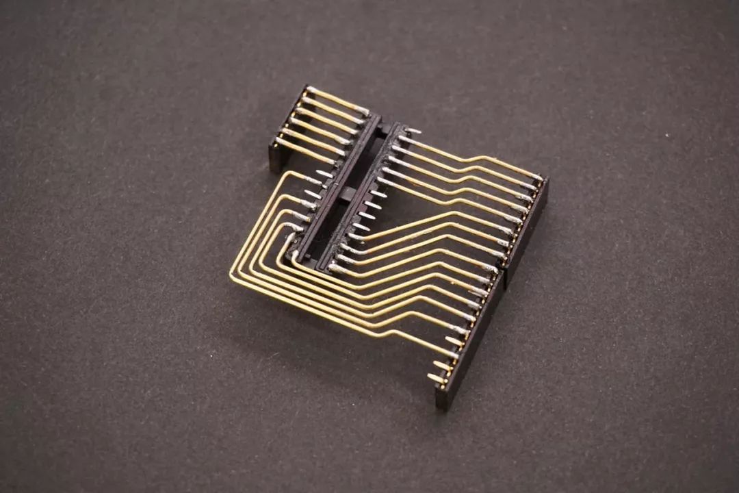
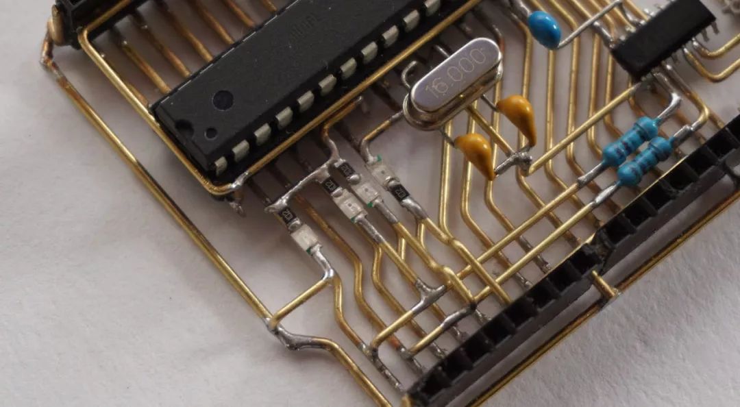
First, start from the MCU and the digital and analog IO pin headers. The Arduino UNO has a clever pin layout that matches very well with the ATMEGA328 28-DIP package layout, eliminating the need for crossed wires.
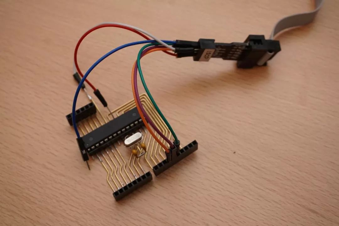
The only external component needed for the ATmega328 to function is an external 16MHz oscillator that requires two 22pF capacitors. The hardware of the ATmega328P is minimal. Now, it can be tested for the first time using an AVR ISCP interface with a USBasp programmer.
Power Circuit
A special fixture was made to hold the socket in the right position, leaving enough space for soldering.
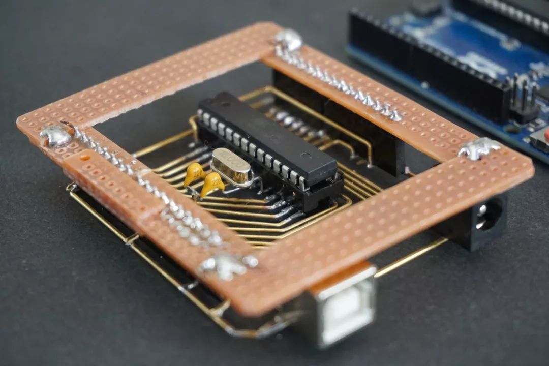
The ATmega328 is powered by 5V. The Arduino UNO has two power input sources – a jack (7-12V) or a USB connector (5V). It also provides 3.3V power for external components. This means two voltage regulators are needed: one to convert 7-12V to 5V and another to convert 5V to 3.3V. Following the recommendations in the datasheet, two AMS1117 5V and 3.3V regulators along with some capacitors were used.
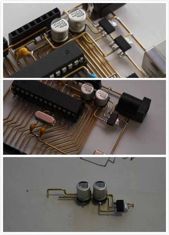
To simplify operations, the power circuit was soldered externally to the board and then placed on the data line. This effectively created two layers of freeform circuit. The auto-selection and reverse current protection parts were omitted as they would complicate the entire process significantly.
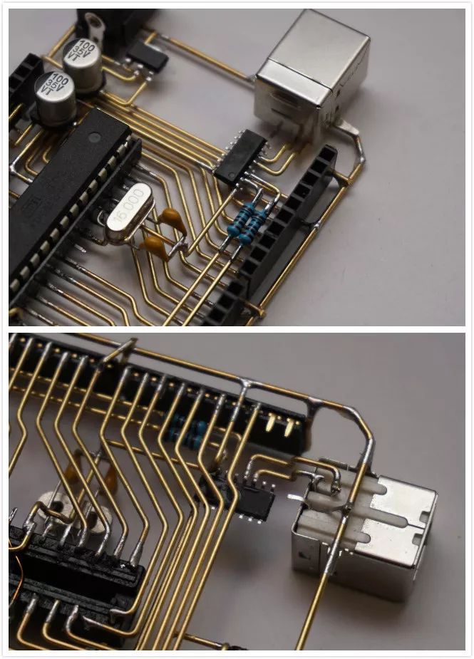
USB to UART Circuit
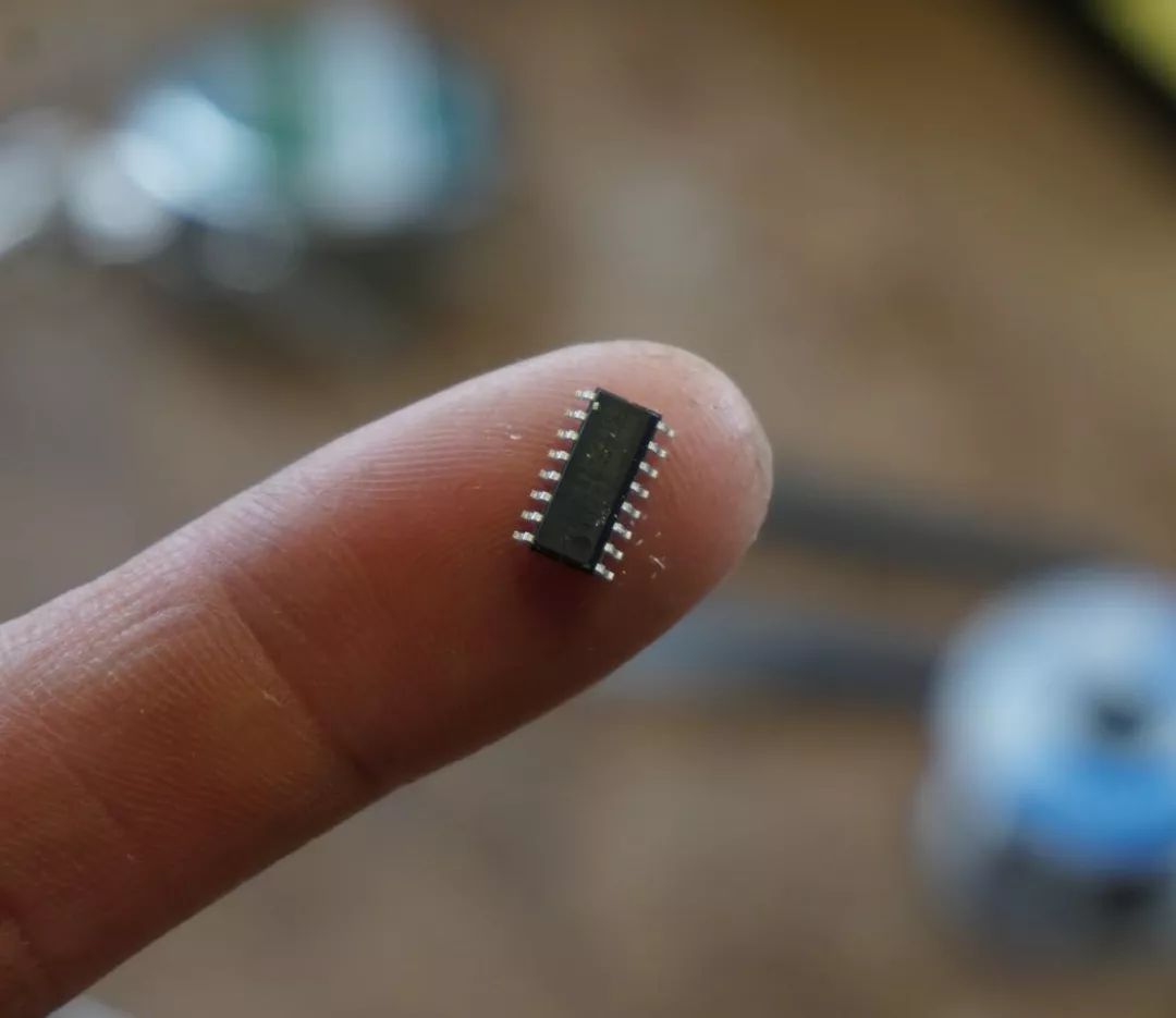
If you want to upload programs through the Arduino IDE without relying on a compiler, this is important. The original Arduino UNO R3 uses ATMEGA8U2-MU, which is great but too small for freeform circuits. It was decided to choose the CH340C chip. It has a suitable SOP-16 package and only requires four external components: debounce capacitor, reset capacitor, and two Tx/Rx line resistors. The fact that no external capacitors are needed greatly simplifies the entire circuit.
LED Indicator Lights
Finally, it was decided to use small SMD 1206 LEDs to indicate power, L, Tx, and Rx communication signals. First, an SMD resistor was soldered to them, and then attempts were made to solder them to the wire. This was tricky. A low-temperature soldering iron must be used, and the issue must be resolved quickly; otherwise, the other side of the SMD component will be unsoldered.
Can Freeduino Light Up?
First, an external power supply was connected to check the power regulator. All voltage levels were good, so the connection continued, and the bootstrap program was uploaded to the chip via the USBasp programmer. To my surprise, the chip communicated on the first attempt. That was a good sign. The external crystal oscillator worked properly, and all pins were correctly connected. The final step was to connect the USB cable and try to upload the blink program. Let’s see:
0/0
00:00/00:06Progress Bar, 0 percentPlay00:00/00:0600:06Fullscreen Playing at speed 0.5x 0.75x 1.0x 1.5x 2.0x High Definition Smooth
Continue Watching
【Dry Goods Sharing】Using Wire to Create a “Circuit Board”, This Operation You Have to Admire!
Reprint,【Dry Goods Sharing】Using Wire to Create a “Circuit Board”, This Operation You Have to Admire!PCB Network ISPCAIGPCAAdded to Top StoriesEnter comment Video Details
Now, encase it in transparent resin to make it less fragile.