STM32Cube is a powerful free development tool provided by STMicroelectronics for developers, enabling them to quickly develop and apply applications on the STM32 platform. STM32Cube mainly consists of two parts:
1. The graphical configuration tool STM32CubeMX, which allows users to graphically configure the interfaces and pins of STM32 chips.
2. Embedded software packages, including HAL libraries, associated protocol libraries, and many complete examples.
Below, we will introduce the usage of STM32Cube step by step. First, download STM32CubeMX from the official website and install it. If prompted to install Java components during installation, do so online. After installing, proceed to install STM32Cube,
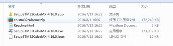
After installation, click New Project to create a new project,

Select Series, Lines, and Package, then choose your MCU model and click OK. You can also select the development board type; we are using the official development board, which can be selected in the Board Selector for convenience,
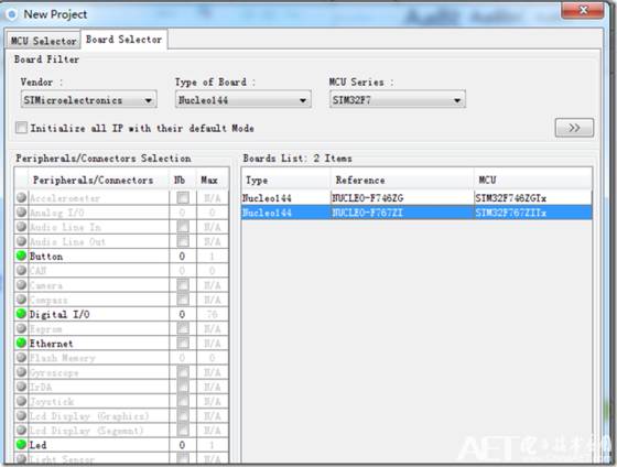
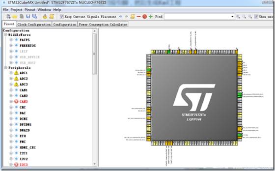
OK, now a new project has been created,
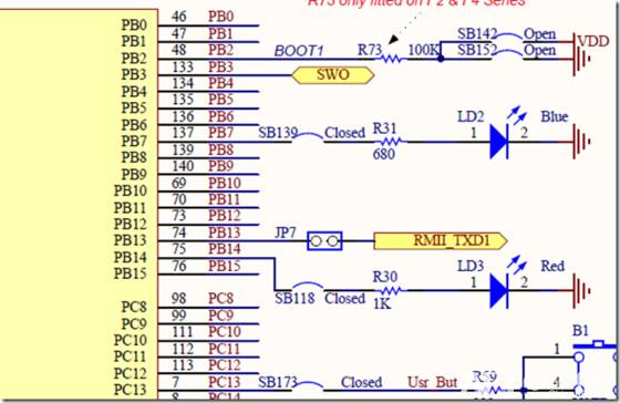
 Here, we also want to configure a project to drive the LED lights based on our development board. As shown, PB7 and PB14 are connected to two LEDs,
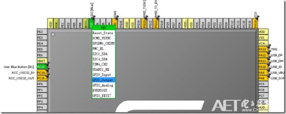
In the STM32CubeMX graphical interface, find these two IOs and select GPIO_Output mode,
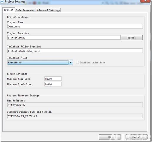
Next, click on Project->Settings in the menu bar, enter the STM32CubeMX project name, save path, and your toolchain/IDE. Keep the settings in Code Generator as default, then click OK,
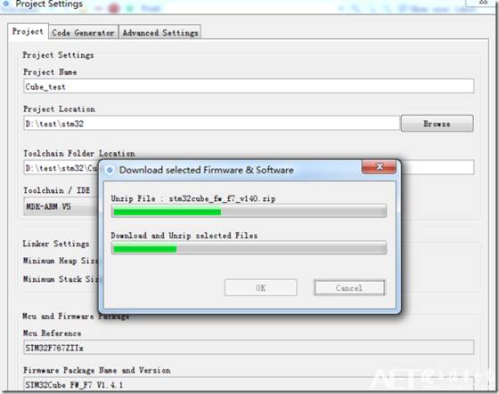
You will be prompted to install the stm32_f7 firmware library, so we will download it online,
After the installation is complete, click on Project->Generate Code in the menu bar to generate the project. The software will automatically create a project for us, configuring the system and pins,
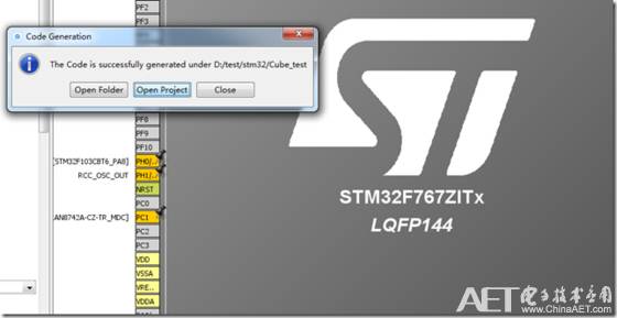
You can click Open Project to open the project,
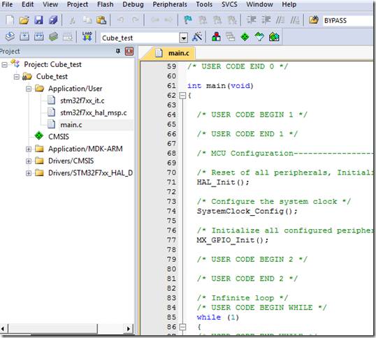
Check the main.c file; the project has already initialized the hardware and clock settings. Here, we only need to add user logic code between /* USER CODE BEGIN 2 */ and /* USER CODE END 2 */. According to the HAL library functions, add the following code:
HAL_GPIO_WritePin (GPIOB, GPIO_PIN_7, GPIO_PIN_SET);
HAL_GPIO_WritePin (GPIOB, GPIO_PIN_14, GPIO_PIN_SET);
Compile and download for debugging, and the LEDs on the board will light up.