Please follow our WeChat subscription account “Finger Motorcycle” for the latest motorcycle maintenance and repair information. Search for ID mscmoto directly in WeChat to follow!
This article mainly discusses several points that are often overlooked when using general-purpose oscilloscope probes.
1. Bandwidth
This is usually marked on the probe. If the probe’s bandwidth is insufficient, it doesn’t matter how wide the oscilloscope’s bandwidth is. This is particularly important when purchasing second-hand oscilloscope probes.
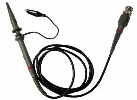
2. Impedance Matching of the Probe
Before using the probe, you should adjust its impedance matching section. Usually, there is an adjustable capacitor near the oscilloscope end of the probe’s test lead (inside the BNC connector). Some probes also have an adjustable capacitor near the probe tip. These are used to adjust the impedance matching of the oscilloscope probe. If the impedance is not matched, the measured waveform will be distorted.
Methods to Adjust Oscilloscope Probe Impedance Matching are as follows:
▲1. Set the oscilloscope’s input to GND, then adjust the Y-axis offset knob to center the scanning line on the oscilloscope. Check if the scanning line is horizontal (i.e., aligned with the oscilloscope’s horizontal midline). If not, adjust the horizontal balance knob (usually analog oscilloscopes have this adjustment hole, which requires a screwdriver to adjust; digital oscilloscopes do not require adjustment).
▲2. Set the oscilloscope’s input to DC coupling and connect the oscilloscope probe to the oscilloscope’s test signal output. Then adjust the time base knob so that the waveform displays about 2 cycles. Adjust the Y-axis gain knob so that the peak-to-peak value of the waveform is about half the screen width. Observe the edges of the square wave to see if they are horizontal.
If overshoot, tilt, steps, or spikes occur, it indicates that the matching capacitor on the test line needs adjustment until both edges of the waveform are horizontal.
▲3. There is a range selection switch on the probe handle. When selecting the ×1 range, the signal enters the oscilloscope without attenuation: when selecting the ×10 range, the signal is attenuated to 1/10 before reaching the oscilloscope. Therefore, when using the oscilloscope in the ×10 range, the reading on the oscilloscope should be multiplied by 10 to get the actual reading.
Additionally, the input impedance in the ×10 range is much higher than in the ×1 range, so when testing signals with weak driving capability, using the ×10 range can provide better measurement.
However, it is important to first use the ×10 range when unsure of the signal voltage to confirm that the voltage is not too high before selecting the correct range for measurement. Developing this habit is very necessary.
▲4. When using the oscilloscope probe, ensure that the ground clip is securely grounded (to the system ground, not true earth). Otherwise, during measurement, a large 50Hz signal will be observed, which is due to the oscilloscope’s ground not being properly connected, resulting in sensing the 50Hz power frequency.

3. Testing Method
Set the oscilloscope to the appropriate scanning frequency and Y-axis gain, then touch the probe tip with your hand; a waveform should be visible, typically a 50Hz signal.
If no waveform appears, check whether the signal wire in the probe is damaged. Then, clip the oscilloscope probe’s ground clip onto the probe tip (or hook), and touch the probe tip again. If the previous signal is not visible (or has a very weak amplitude), the ground line of the probe is good; otherwise, it is damaged.
If the wire connected to the clip is open, it can usually be re-soldered; if necessary, it can be replaced. Note that the ground clip’s wire should not be too long, as this can easily introduce interference (especially in high-frequency small signal environments).
The oscilloscope probe’s ground clip should be close to the measurement point, especially when measuring high-frequency, low-amplitude signals. Long ground wires can form a loop, acting like a coil that senses the electromagnetic field in the environment.
Additionally, when the ground current in the system is high, a voltage drop will occur on the ground wire. Therefore, the oscilloscope probe’s ground should be connected to a ground point near the measurement point.
Lastly, regarding grounding, if the tested device has a protective grounding system, do not connect the oscilloscope’s power supply ground terminal to ground again, as this poses a risk of damaging the device.
When connecting the test leads to the tested device, it is best not to power on. If unavoidable, do not touch the metal parts of both the test leads and the tested device simultaneously, as there is a risk of electric shock (especially for analog oscilloscopes, particularly those using CRT tubes).
Further Reading:
Tips | DIY 5000V Motorcycle Maintenance High Voltage Pliers
Can Oscilloscopes Only Check Circuits? Who Says So!
How to Adjust Motorcycle Carburetors to Optimal Condition
The Difficult-to-Start Star in Winter – Smart Ignition Device
Official WeChat subscription account of Motorcycle China Network

WeChat ID: mscmoto

Long press the QR code to donate