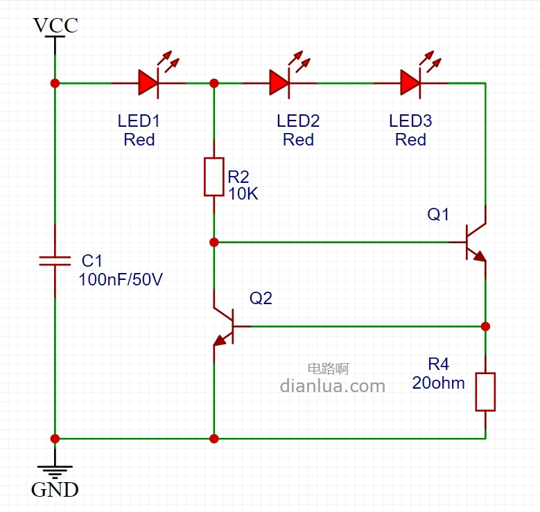
A friend made an LED constant current circuit board and found that the capacitor exploded.With the delivery time approaching and mass production about to start, there was a lot of urgency, so help was sought in the group.This is the schematic of the problematic circuit board: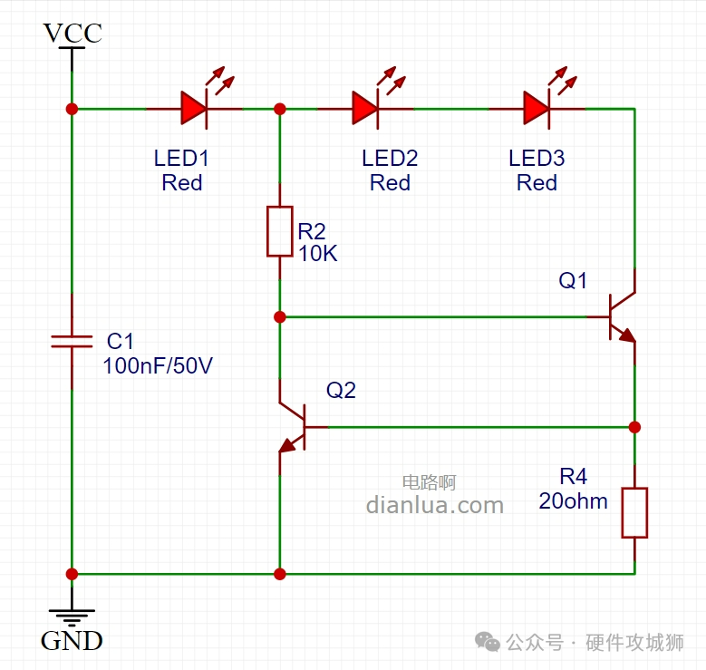 The capacitor that exploded is C1, which is an MLCC capacitor, specifically a surface-mounted multilayer ceramic capacitor:
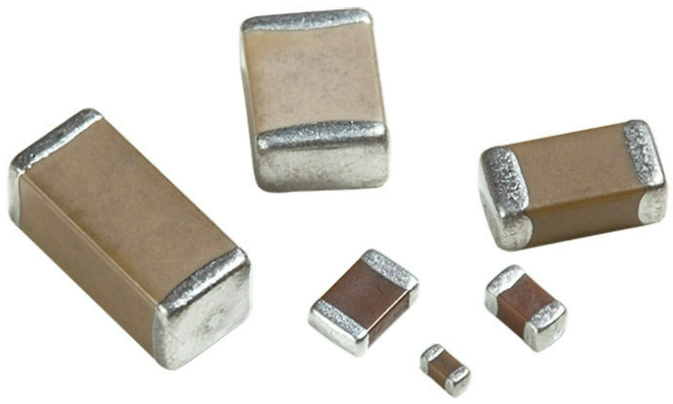 Simulation diagram:
 The circuit itself seems to have no issues, below is a restoration of the diagnosis process by various experts, which is very exciting.Due to privacy concerns, the chat screenshots have been anonymized.
 At this point, a lot of information has been provided, readers might as well make their own judgment, and see if they can solve the case?The discussion continues in the group, and the answer will be revealed soon.
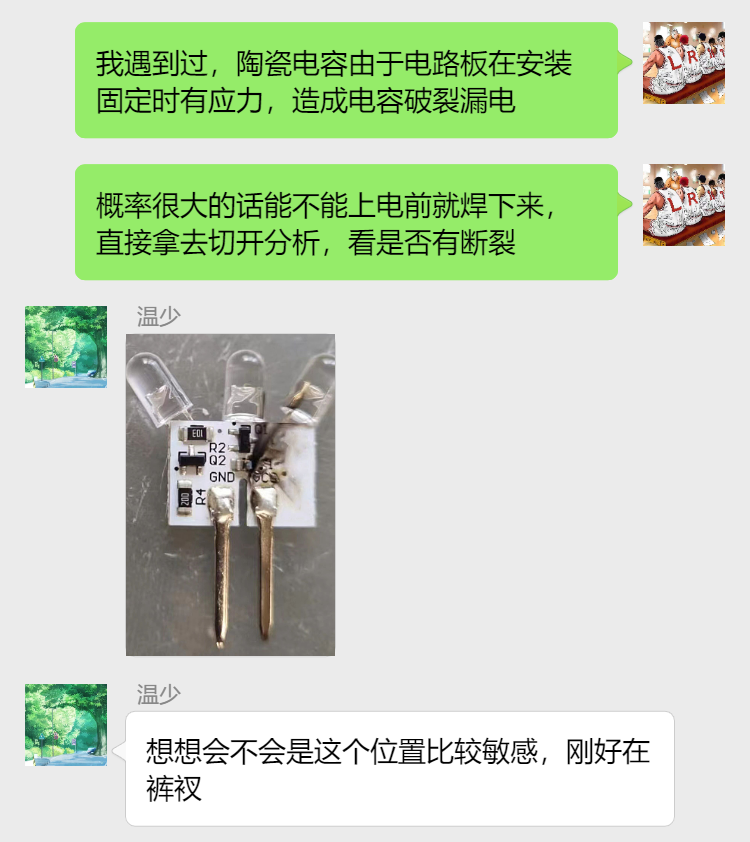 The images shared in the group are as follows, the capacitor C1 is placed horizontally in the middle of the PCB and has burned out:
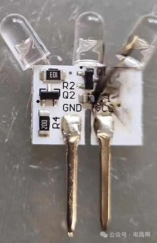 With this physical image, combined with previous discussions, the answer is already quite clear.
 The specifications mentioned by Long Ge are clearly stated, the following two images are from the Murata MLCC capacitor specification book.
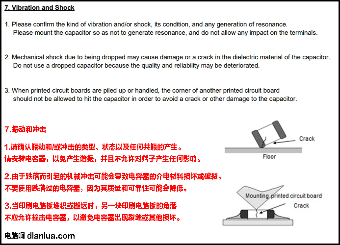 The second image is as follows, there are some other explanations, which will not be captured here, it is recommended that everyone carefully read the specification book.
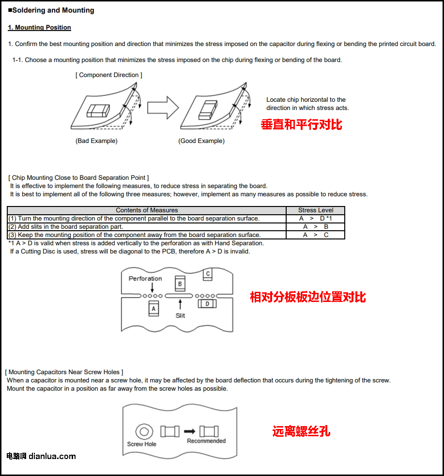 The problem encountered in this article is definitely not an isolated case, the experts involved in the diagnosis have also encountered similar issues.Unfortunately, such problems will continue to occur in the future, and how to avoid them as much as possible, I believe this article can serve as a warning for everyone.Further reading: “Case Study: Circuit Principles of LED Constant Current Circuit”
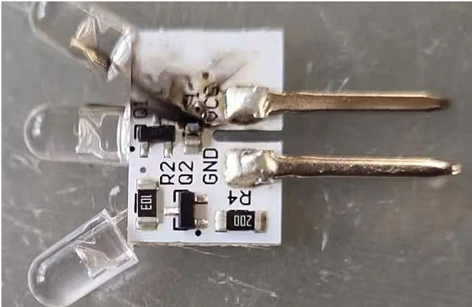 Restoring its circuit schematic:
Since it is said to be an LED constant current circuit, how does it achieve constant current?
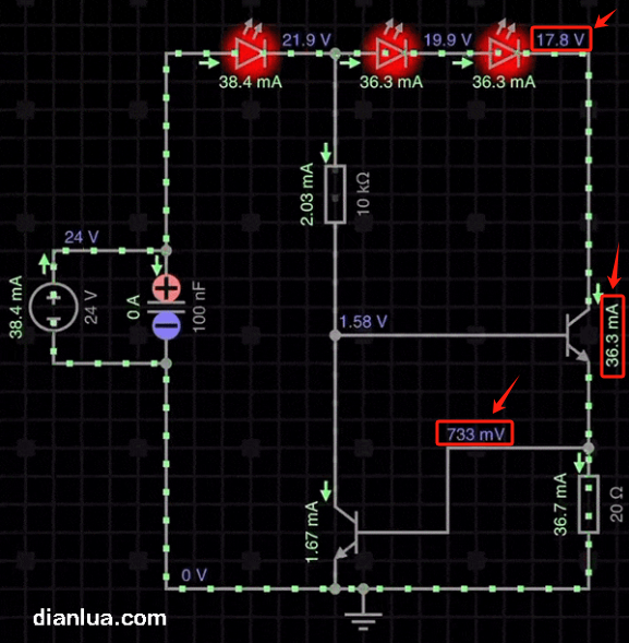
To visually demonstrate its “constant current” effect, please see the following simulation animation.
When powered by 24V:
The current flowing through the LED is:
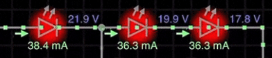
When powered by 12V:
The current flowing through the LED is:

When powered by 24V and 12V, the voltage difference is double, but the current flowing through the LED does not differ much, meaning the current is basically “constant”.
Next, taking 12V power supply as an example, we will analyze the circuit principle for achieving constant current.
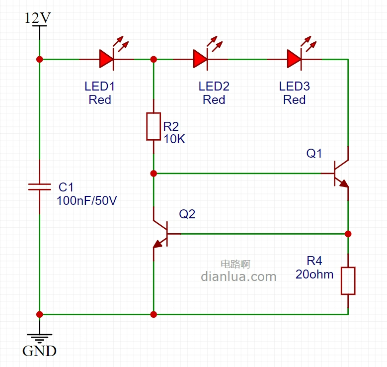
As the saying goes, know your enemy and know yourself, and you will never be defeated. First, identify the known conditions for achieving constant current:
- Supply voltage 12V;
- LED forward voltage drop (Vf) is approximately 2.1V;
- The voltage difference (Vbe) between the base and emitter of the transistor when it is conducting is approximately 0.7V.
From here, it becomes relatively simple; starting from the known conditions, we can derive the unknown quantities.
1. Starting from 12V, each LED reduces the voltage by 2.1V, we can determine the voltages at the following three circuit nodes to be 9.9V, 7.8V, and 5.7V:
2. Starting from ground (GND), each time we pass through the emitter and base of a transistor, the voltage increases by 0.7V:

Thus, the voltages at all nodes in the circuit are determined:
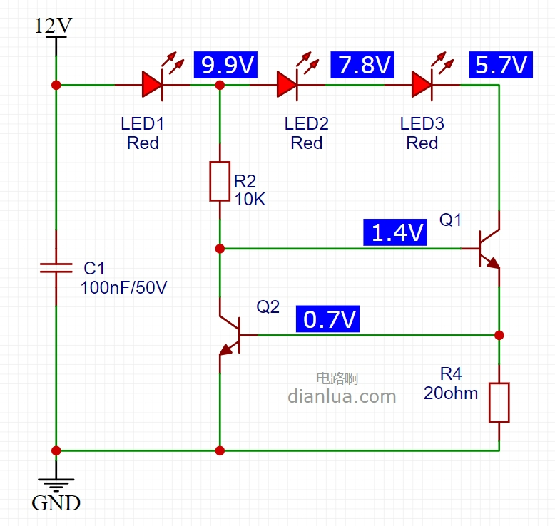
The ability to achieve constant current is due to the resistor R4 being clamped to 0.7V by the base-emitter (be) of transistor Q2, thus the current flowing through it is fixed at:
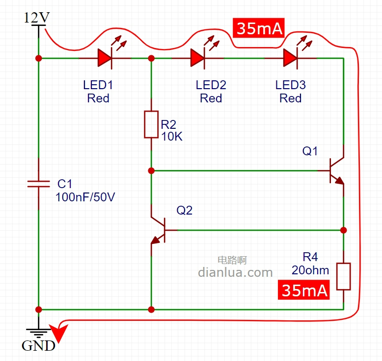
0.7V / R4 = 0.7V / 20ohm = 35mA
Since the base of the transistor only draws a very small current, it can be ignored, so this 35mA is essentially the current flowing through transistor Q1, which is also approximately the current flowing through the LED:
The theoretical analysis above is basically consistent with the results shown in the simulation animation.
According to the principle of constant current in this circuit, to change the constant current value, simply adjust the resistance R4.
It is important to note whether the power dissipation of transistor Q1 is too high. The power dissipation Pc of the transistor is equal to:
Vce * Ic
Where Vce is the voltage difference between the collector and emitter.
Ic is the current flowing through the collector.
For SOT-23 packaged transistors:
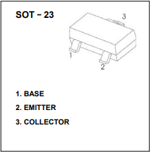
The maximum power dissipation it can withstand is relatively small, as stated in the datasheet, it is 200mW:
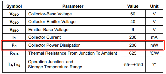
Readers can calculate whether the power dissipation of Q1 exceeds 200mW under 24V power supply conditions. (Just looking without practicing will reduce the effectiveness, everyone can try to get hands-on)
Tip: Use the values indicated by the red arrows in the image below for calculations.
Additionally, resistor R2 is used to provide a current path for the base of transistor Q1 and to provide a current path for the collector of transistor Q2:
— End —
This account maintains neutrality regarding all original and reprinted articles’ statements and viewpoints, and the articles are provided for readers’ learning and communication. The copyright of the articles, images, etc., belongs to the original authors. If there is any infringement, please contact for deletion.

-Recommended Reading-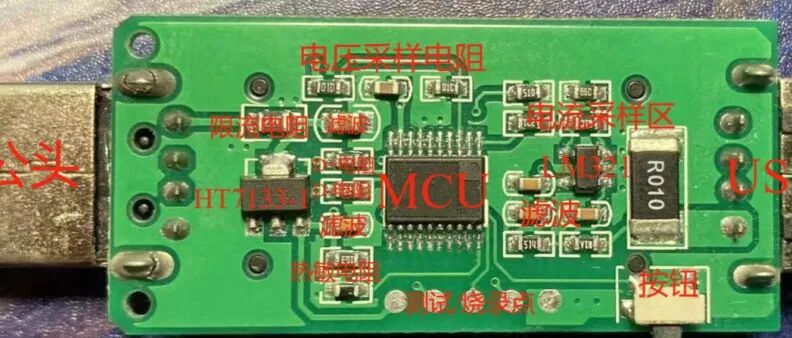
Disassemble a 27 yuan free shipping USB power meter! Can still earn 10 yuan! And found a polished MCU~

Secretly disassembled my son’s “Porsche”, clean wiring, full texture!
Support quality content, please “share, like, and view”👇