Today, let’s delve into a seemingly basic yet often overlooked topic — what exactly happens from the moment you press the reset button until your <span>main()</span> function begins execution?
Startup Process Overview: The Journey of System Awakening
Imagine your MCU as a robot just awakened. It needs to get dressed (load the stack), understand its mission (read the vector table), and then it can start working (execute code). This process is precise and elegant:

Moment of Power-On: Hardware Takes Control
At the moment the power button is pressed, the hardware circuitry takes complete control and executes the following steps:
- 1.Register Reset: Like “reprogramming” the robot
- 2.Obtain Stack Address: Read the first 32-bit value from the current VTOR (Vector Table Offset Register) as the MSP
- 3.Read Reset Vector: Get the next value from VTOR+4, which is the address of your Reset_Handler function
- 4.Jump to Execution: The PC jumps to the reset vector and starts executing the startup code
Tip: The physical Flash starting address of the STM32 series is actually 0x08000000, mapped to 0x00000000 through address aliasing or mapping mechanisms. When debugging startup issues, remember to check both addresses!
Interrupt Vector Table: The Core of Interrupt Management
Differences in Vector Tables Across Cortex-M Cores
| Exception Type | Cortex-M0/M0+ | Cortex-M3/M4/M7 | Remarks |
| System Exceptions | Up to 16 | Up to 16 | M0/M0+ lacks some advanced exception types |
| External Interrupts | Up to 32 | Up to 240 | The actual number is determined by the specific chip |
| Vector Table Entries | Up to 48 | Up to 256 | Alignment requirements differ: M0/M0+ requires 32-byte alignment, M3/M4/M7 require 128-byte or 256-byte alignment (depending on the chip) |
Your firmware must ensure this table is in the correct location! Most chips require it to be at the beginning of Flash (0x08000000 or other startup regions).
// Check if your vector table looks like this in your code?
__attribute__ ((section(".isr_vector")))
void * const g_pfnVectors[] = {
    (void*)&_estack,         // Stack top pointer
    (void*)Reset_Handler,    // Reset handler function
    (void*)NMI_Handler,
    (void*)HardFault_Handler,
    (void*)MemManage_Handler,  // ⚠️ Note: M0/M0+ does not have this advanced exception
    (void*)BusFault_Handler,   // ⚠️ Note: M0/M0+ does not have this advanced exception
    (void*)UsageFault_Handler, // ⚠️ Note: M0/M0+ does not have this advanced exception
    // More interrupt handler functions...
};
Reset_Handler: The Soul of Startup
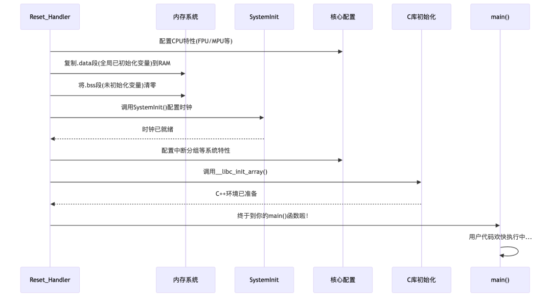
If we compare the startup process to a movie, then <span>Reset_Handler</span> is the absolute protagonist! Its task list is long:
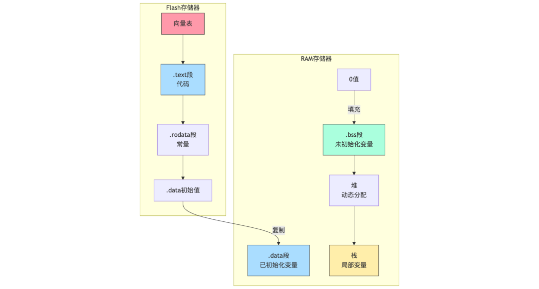
Programs and initial values are stored in Flash, but the program needs to operate on data in RAM during execution. Imagine your program data is divided as follows:
- •Code (.text) + Constants: Stored in Flash, read-only
- •Initialized Data (.data): Global variables that require specific initial values, initial values stored in Flash, copied to RAM at runtime
- •Uninitialized Data (.bss): Global variables defaulting to 0, only need to be zeroed in RAM
Here is a complete implementation of <span>Reset_Handler</span>:
void Reset_Handler(void) {
    // 1. [Optional] Initialize CPU features
    #if (__FPU_PRESENT == 1) && (__FPU_USED == 1)
        // Enable Floating Point Unit (FPU)
        SCB->CPACR |= ((3UL << 10*2) | (3UL << 11*2));
    #endif

    // 2. Copy initialized data from Flash to SRAM (.data section)
    uint32_t *pSrc = &_sidata;
    uint32_t *pDest = &_sdata;

    // Copy by 32-bit words, handling alignment
    while (pDest < &_edata) {
        *pDest++ = *pSrc++;
    }

    // 3. Zero the .bss section, ensure 32-bit writes for performance optimization
    pDest = &_sbss;
    while (pDest < &_ebss) {
        *pDest++ = 0;
    }

    // 4. [Optional] Configure MPU protection regions
    #ifdef USE_MPU
        MPU_Config();
    #endif

    // 5. System clock initialization
    SystemInit();

    // 6. Configure interrupt priority grouping
    NVIC_SetPriorityGrouping(NVIC_PRIORITYGROUP_4);

    // 7. C/C++ runtime initialization
    __libc_init_array();

    // 8. Jump to user code
    main();

    // 9. Prevent undefined behavior from main returning
    while (1) {
        // Optional: enter low power mode
        // __WFI();
    }
}
In-Depth Analysis: The above code illustrates why the initialization of
<span>.data</span>and<span>.bss</span>must occur before any other function calls. Imagine if you called SystemInit() before initializing global variables, and SystemInit() internally relies on a global variable, what would happen? This is why professional startup code must follow a strict order!
Memory Layout and Linker Script
The variables used in the above initialization code, such as <span>_sidata</span>, <span>_sdata</span>, etc., are defined by the linker script:
/* Key part of the linker script */
SECTIONS
{
    .text :
    {
        KEEP(*(.isr_vector))  /* Vector table must be at the front */
        *(.text)              /* Code section */
        *(.rodata)            /* Read-only data section */
        . = ALIGN(4);         /* Ensure 4-byte alignment */
    } >FLASH

    /* .data section position in Flash */
    _sidata = LOADADDR(.data);

    .data :
    {
        _sdata = .;            /* Start address of .data section in RAM */
        *(.data)               /* Global initialized variables */
        . = ALIGN(4);
        _edata = .;            /* End address of .data section */
    } >RAM AT> FLASH

    .bss :
    {
        _sbss = .;             /* Start address of .bss section */
        *(.bss)                /* Global uninitialized variables */
        *(COMMON)              /* Common area */
        . = ALIGN(4);
        _ebss = .;             /* End address of .bss section */
    } >RAM
}
Visualizing Memory Layout:
I once encountered a project where global initialized variables were always corrupted during program execution. After investigation, it was found that the linker script was modified but
<span>_sidata</span><span> was not set correctly, causing the </span><code><span>.data</span><span> section to be copied from the wrong Flash address to RAM! This reminds us that the linker script and startup code must work in strict coordination.</span>
Clock Configuration: Installing the “Engine” for the System
<span>SystemInit()</span> function typically performs the following common initialization operations:
- •Clock Configuration: Such as configuring system clock, peripheral clock, etc.
- •Flash Access Configuration: Configuring Flash wait states, prefetch, cache, etc., to optimize code execution efficiency.
- •Power Management Configuration: Configuring voltage regulators, low power modes, etc.
- •Cache and TCM (Tightly Coupled Memory) Initialization (if present): For Cortex-M cores with Cache or TCM, the
<span>SystemInit()</span><span> function may also be responsible for initializing Cache and TCM.</span>
Clock configuration is also the source of many bizarre issues! Unstable or incorrectly configured clocks can lead to:
- • Serial port baud rate offsets
- • Abnormal ADC sampling
- • Timer precision degradation
- • Even the entire system restarting inexplicably
Differences in Compiler Toolchains: Different Paths to the Same Goal
Major manufacturers have their own “characteristic” startup processes, but the ultimate goal is to initialize the system and call main(). Understanding these differences is crucial for project porting:
GCC (arm-none-eabi-gcc)
// In startup_stm32f4xx.s or similar file
.section .text.Reset_Handler
.weak Reset_Handler
.type Reset_Handler, %function
Reset_Handler:
    ldr   r0, =_estack
    mov   sp, r0          /* Set stack pointer */

    bl    SystemInit      /* System initialization */

    /* The following usually calls C functions to complete memory initialization, etc. */
    bl    _start_c        /* Jump to C part */

// In C file
void _start_c(void) {
    // Data section initialization
    // ...

    // C++ support
    __libc_init_array();

    // Jump to main
    main();

    // Main function return handling
    while(1);
}
Keil MDK (ARMCC)
__asm void Reset_Handler(void) {
    IMPORT  __main

    LDR     R0, =__main
    BX      R0            /* Jump to ARMCC library code */
}

// __main is responsible for:
// 1. Initializing RAM (.data, .bss)
// 2. Calling SystemInit()
// 3. Executing C++ static initialization
// 4. Calling main()
IAR EWARM
void Reset_Handler(void) {
    __iar_program_start();
    /* Call IAR library function to complete all initialization and jump to main */
}Tip: When porting projects between different compilers, the startup code is often the most problematic. For example, differences in .bss section initialization may lead to some global variables not being correctly zeroed, resulting in hard-to-debug random issues.
Advanced Startup Techniques: Becoming an Expert in the Startup Process
Vector Table Relocation: Flexibly Responding to Various Scenarios
Vector table relocation is a key technology for implementing bootloaders, firmware upgrades, and other advanced functions:
// Assume we relocate the vector table to RAM (0x20000000)
// 1. Ensure the vector table meets alignment requirements (usually 2^N, such as 256-byte alignment)
#define VECTOR_TABLE_ALIGNMENT  0x100  // 256-byte alignment

// 2. Allocate space in RAM and align
__attribute__((aligned(VECTOR_TABLE_ALIGNMENT)))
uint32_t ram_vector_table[48];  // Adjust size according to specific MCU

// 3. Copy the vector table
void relocate_vector_table(void) {
    // Get the original vector table address in ROM
    uint32_t *rom_vectors = (uint32_t*)SCB->VTOR;

    // Copy vector table contents to RAM
    for(int i = 0; i < 48; i++) {
        ram_vector_table[i] = rom_vectors[i];
    }

    // Set VTOR to point to the new vector table (ensure alignment)
    SCB->VTOR = ((uint32_t)ram_vector_table & SCB_VTOR_TBLOFF_Msk);

    // Add memory barriers to ensure the setting takes effect
    __DSB();
    __ISB();
}
Practical Application Scenarios:
- •Bootloader Implementation: The bootloader loads the application and then relocates the vector table
- •Dynamic Interrupt Handling: Modifying interrupt handler function addresses in RAM
- •Software Partitioning: Loading multiple applications in different memory areas
Multi-Level Boot and Secure Boot
Modern embedded systems often use multi-level boot to enhance security and flexibility. Key points for implementing secure boot:
- 1.Firmware Integrity Verification: Using CRC32/SHA256 algorithms to verify firmware
- 2.Signature Verification: Verifying firmware source through asymmetric encryption
- 3.Secure Boot Flags: Protection mechanisms to prevent downgrade attacks
- 4.Sensitive Data Erasure: Clearing encrypted keys and other information during the boot process
Fast Boot Optimization: Enhancing User Experience
How to shorten the time from power-on to functionality available?
- 1.Minimize Initialization: Delay non-critical peripheral initialization
// Use weak definitions and flags to allow delayed initialization __weak void peripheral_init(void) { // Basic initialization } // Delay full initialization in main function void full_peripheral_init(void) { // Complete initialization } - 2.Selective Initialization of .data Section: Only initialize critical variables
// Create a special section for critical data in the linker script .critical_data : { _scritical_data = .; *(.critical_data) // Use special section attributes to mark critical variables _ecritical_data = .; } >RAM AT> FLASH // Only initialize critical data section, delay initialization of others void Reset_Handler(void) { // Only initialize critical data init_critical_data(); // Initialize remaining data in the background after entering main } - 3.Clock Optimization: Start with the internal RC oscillator, then switch to PLL
void SystemInit(void) { // Start with HSI (internal oscillator) to ensure quick system startup // ... // Switch to PLL high-speed clock in background tasks // schedule_background_task(switch_to_pll); } - 4.Flash Prefetch and Cache Optimization: Proper configuration to enhance code execution efficiency
// Enable instruction and data cache, configure prefetch
FLASH->ACR = FLASH_ACR_PRFTEN | FLASH_ACR_ICEN |
             FLASH_ACR_DCEN | FLASH_ACR_LATENCY_5WS;
Common Startup Issues and Solutions
The following startup issues are the most common:
| Problem Phenomenon | Possible Cause | Debugging Method | Solution |
| Does not run on power-on | Incorrect vector table | Use a debugger to check the content at address 0x00 | Check the linker script and vector table definitions, ensure they are at the correct address |
| Immediately hardfault | Improper stack setup | Observe the initial value of MSP, check the CFSR register before startup | Confirm the value of _estack is correct, increase stack space, check stack alignment (8 bytes) |
| Random crashes | Incomplete .data/.bss initialization | Use memory view to check global variable values | Complete the memory initialization part in the startup code, ensure all sections are correctly initialized |
| Some peripherals malfunction | Incorrect clock configuration | Check RCC register status and clock frequency | Review clock tree settings in SystemInit(), ensure peripheral clocks are enabled |
| C++ object construction fails | Missing C++ initialization call | Set breakpoints to check if constructors are executed | Ensure __libc_init_array() or equivalent function is called |
| Slow startup on power-on | Redundant initialization process | Use performance counters to analyze the startup process | Optimize the startup process, delay non-essential initialization, optimize Flash access wait states |
Startup Fault Debugging Tips
- 1.Use simple GPIO to indicate startup stages
void Reset_Handler(void) { // Configure a debug pin as early as possible RCC->AHB1ENR |= RCC_AHB1ENR_GPIOAEN; GPIOA->MODER |= GPIO_MODER_MODER5_0; // PA5 output mode GPIOA->BSRR = GPIO_BSRR_BS5; // Stage 1: Set pin high init_data_bss(); GPIOA->BSRR = GPIO_BSRR_BR5; // Stage 2: Set pin low SystemInit(); GPIOA->BSRR = GPIO_BSRR_BS5; // Stage 3: Set pin high again // ... and so on } - 2.Use DWT performance counters to accurately measure startup time
void measure_startup(void) {
    // Enable DWT
    CoreDebug->DEMCR |= CoreDebug_DEMCR_TRCENA_Msk;
    DWT->CTRL |= DWT_CTRL_CYCCNTENA_Msk;
    DWT->CYCCNT = 0;

    // Measure target function
    SystemInit();
    uint32_t cycles = DWT->CYCCNT;

    // Convert to time (assuming clock is 168MHz)
    float time_ms = (float)cycles / 168000.0f;

    // Output results via serial port or other means
}
Conclusion: The Significance of Mastering the Startup Process
Understanding the Cortex-M startup process not only helps you solve tricky bugs but also allows you to:
- • Design more reliable systems
- • Achieve faster startup speeds
- • Develop more secure firmware
- • Port code more easily
As embedded developers, we should understand the startup process as well as we understand our code. As the saying goes, “Know yourself and know your enemy, and you will never lose a battle.” Only by truly understanding how the system starts can we develop truly stable and reliable embedded products. The best code is not just written; it is well thought out, thoroughly tested, and understood in its operating environment. The startup process is the beginning of it all!
Frequently Asked Questions
Q1: How can I modify the Cortex-M startup code to speed up startup?A:You can remove unnecessary initialization steps, optimize clock configuration in SystemInit(), reduce C++ global constructors, and use linker optimizations to minimize the amount of data that needs to be initialized.
Q2: How can I add custom initialization code in the reset handler?A:You can add custom function calls after SystemInit() and before main(), or use the attribute((constructor)) attribute to have the function automatically called during C library initialization.
Q3: Why do I sometimes encounter hardfault instead of executing my code?A:The most common reasons are incorrect vector table configuration, improper stack pointer setup, or memory access violations. Check the vector table and stack settings in the linker script and startup file.
Q4: What is the typical startup speed of Cortex-M?A:The startup time from reset to the main() function is typically a few milliseconds to tens of milliseconds, depending on clock configuration, Flash wait states, and the amount of initialization data. With optimization, it can be reduced to sub-millisecond levels.
Q5: How can I ensure the security of the startup code to prevent unauthorized access or tampering?A:You can implement secure boot mechanisms, such as code signature verification, enable read protection (RDP), configure the correct Flash lock options, and use secure boot features on devices with TrustZone support.
Feel free to share your experiences and tips in the comments section, let’s learn and progress together!Previous Reviews Comprehensive Analysis of ARM Cortex-M Interrupt HandlingC Preprocessing: The Swiss Army Knife of Embedded DevelopmentAdvanced Embedded Debugging: From Manual to Automated HardFault Investigation GuideStill stuck in 996? Here are five tips to elevate your code quality and say goodbye to endless debugging!This “simple” C code hides so many secrets you didn’t know!