This article mainly introduces the composition of electronic components in automotive architecture from the perspective of software development, and explains why embedded software development is necessary for automobiles.

In new energy vehicles, when we shift to drive and press the accelerator, the car moves forward, and when we press the brake, the car stops. The signal generated by pressing the accelerator is transmitted to the ECU (Electronic Control Unit), also known as the “driving computer”.
In simple terms, the ECU is a system composed of an MCU plus some necessary peripheral circuits, which can process various input signals (sensor signals, in-vehicle network signals, etc.) and then output signals (control signals for actuators, in-vehicle network signals, etc.). Its purpose is to control the driving status of the vehicle and realize its various functions. It mainly uses data collection and exchange from various sensors and buses to judge the vehicle’s status and the driver’s intentions and control the car through actuators. The following is a physical picture of one of the ECUs.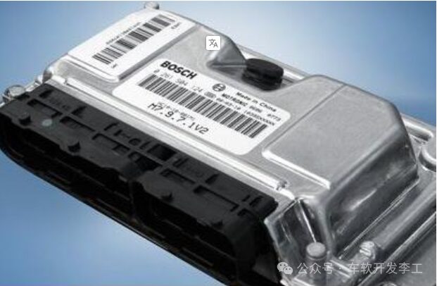
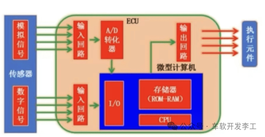
The ECU consists of four parts: input circuit, A/D converter, microcomputer, and output circuit. The ECU is similar to the CPU of a computer.
Functions of the Input Circuit:
-
Filtering out noise from sensor input signals
-
Converting sine waves to square waves
-
Converting to input level
Functions of the A/D Converter:
Some sensors on the car generate digital signals, while others generate analog signals. The A/D converter converts analog signals into digital signals.
Once the digital signal is generated, the microcomputer processes it.
The microcomputer consists of RAM, ROM, I/O interfaces, and a CPU. The function of the microcomputer is to process the various signals sent by the sensors according to the needs of the work, using the program (the program processed by the microcomputer) and data in memory for calculations, and then send the processing results to the output circuit.
Output Circuit:After the microcomputer issues a response command, the actuator cannot execute it immediately. Since the microcomputer outputs a low-voltage digital signal, this signal generally cannot directly drive the actuator. The output circuit’s role is to convert the digital signal output by the microcomputer into an output signal that can drive the actuator, usually using high-power transistors.Function of the Output Circuit(Summary):Convert the digital signal output by the microcomputer into an output signal that can drive the actuator. The output circuit typically uses high-power transistors controlled by the microcomputer’s output signals.
 Why is automotive embedded development necessary?
Using the pressing of the accelerator as an example, when the accelerator is pressed down, the relevant sensor signals are sent to the ECU. At this point, the microcomputer in the ECU will process the sensor signals based on programming, and the process of programming is the process of embedded software development.
Like ordinary microcontrollers, the ECU is composed of a microcontroller (MCU), memory (ROM, RAM), input/output interfaces (I/O), analog-to-digital converters (A/D), and other large-scale integrated circuits.
Functions of the ECU
1. Parameter Control: The function of the ECU is to calculate the vehicle’s driving status through various sensors and control the parameters accordingly.
2. Fault Self-Diagnosis and Protection Function: When the system malfunctions, it can automatically record fault codes in memory and adopt protective measures to read alternative programs from the inherent programs to maintain operation.
Common Types of ECU
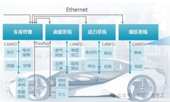
The control range of the ECU has expanded to include cruise control, lighting control, airbag control, suspension control, exhaust control, brake control, EGR, and boost pressure control. As the number of electronic components in vehicles increases, the wiring becomes more complex. To simplify circuits and reduce costs, multiple ECUs in a vehicle are now connected through the CAN bus, forming a network system.
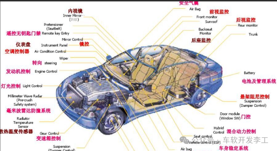
Nowadays, ECUs have become one of the most common components in vehicles. Depending on their functions, they can be divided into different types. The most common types of ECUs are as follows:
-
BCM (Body Control Module): Mainly controls the electrical systems of the vehicle body, such as lights, wipers, washing systems, door locks, power windows, sunroofs, power mirrors, remote control, etc.
-
ESP (Electronic Stability Program): ESP helps maintain optimal stability of the vehicle under various conditions, especially in cases of oversteering or understeering. ESP is a term used by Bosch, while other manufacturers have their own names for similar systems, such as Nissan’s VDC (Vehicle Dynamic Control), Toyota’s VSC (Vehicle Stability Control), Honda’s VSA (Vehicle Stability Assist Control), and BMW’s DSC (Dynamic Stability Control). Many mid-to-high-end joint venture and domestic vehicles are now equipped with this module.
-
BMS (Battery Management System): This controller is specifically designed for electric vehicles or hybrid vehicles equipped with power batteries. Its main function is to improve battery utilization, prevent overcharging and over-discharging, extend battery life, and monitor battery status.
-
VCU (Vehicle Control Unit): This is the controller for the power system of hybrid and pure electric vehicles, responsible for coordinating the work of the engine, drive motor, transmission, and power battery to improve the vehicle’s economy, performance, safety, and reduce emissions.
 ECU Software Development Process
When the accelerator is pressed down, the relevant sensor signals are sent to the VCU domain in the ECU classification. As a core component of new energy vehicles, the VCU is responsible for managing the energy distribution of the entire vehicle, including torque management, motor-battery coordination management, charging management, and fault diagnosis. Based on collected parameters such as driver operation commands, vehicle speed, motor speed, SOC, and water temperature, it selects the optimal energy output mode for the new energy vehicle, achieving the optimization goals for the motor, battery, and transmission system. Therefore, a high-performance, low-cost VCU has a significant impact on the performance of new energy vehicles in terms of power, economy, safety, and more.
After receiving the accelerator’s sensor signal, the VCU processes it based on the collected physical signals and received CAN signals. It then recognizes the driver’s intentions through signals and programming, including:
-
Shift intention
-
Acceleration intention
-
Brake intention
-
Driving mode switch intention
-
Steering intention
Based on the driver’s intentions, the VCU program performs the following calculations:
-
The VCU calculates the required torque based on the driver’s intentions (accelerator pedal, gear position, etc.)
-
The VCU calculates the required torque for driving mode switch intentions
-
The VCU calculates and controls the vehicle’s starting torque
-
The VCU calculates and controls the crawling torque
-
The VCU calculates and controls the hill-hold torque
-
The VCU calculates and controls the energy recovery torque
-
The VCU calculates and controls the torque for cruise control
-
The VCU calculates and controls the torque for limp mode
-
The VCU limits the overall vehicle torque
-
The VCU performs damping processing on the overall vehicle torque
-
The VCU performs gradient processing on the overall vehicle torque
-
The VCU performs smoothing processing on the torque
-
The torque control process ensures that it does not affect personnel safety and vehicle safety while considering user experience and minimizing energy consumption.
VCU Program Logic Overview
The entire vehicle drive system of the electric vehicle consists of the motor and the motor control system, communicating with the vehicle network via CAN bus.
1) The VCU obtains the final torque information by collecting pedal opening signals and gear position signals, followed by torque calculation. The torque information is sent from the VCU to the MCU via the CAN bus, and the MCU executes the corresponding actions upon receiving the control signals.
2) Depending on the vehicle’s operating conditions, the motor operation modes are divided into electric mode and generation mode. In electric mode, the vehicle operates in a driving state; in generation mode, the vehicle operates in coasting or braking state, achieving brake energy recovery.
3) During operation, the motor control system reports status information and fault information to the VCU in real-time, and promptly handles any system faults. Upon receiving the various messages from the MCU, the VCU makes reasonable control decisions for the entire vehicle system based on the content of the information.
The above process implements a complete software function for the vehicle accelerator.
Conclusion:
First of all, a car is composed of a series of ECU (similar to microcontrollers) electronic devices. Since the signals collected by the sensors need to be processed by programs to realize the functions of the car, the demand for embedded software development in automotive applications arises.
This article ends here. The next article will introduce what AUTOSAR is in automotive embedded development through an example of an electronic thermometer.