Click the blue text to follow us
Hello everyone
Welcome to 【Advanced Training Industrial Control】
Session Three
Arduino Maker Series Basic Application Explanation
Lesson Three
The Components of Arduino Development Boards
Those who have learned about Arduino know that: Arduino consists of a microcontroller and a development environment. In the last session, we also learned about the installation of the Arduino development environment (Arduino IDE) software and drivers. Next, I will explain what the hardware platform of Arduino (Arduino development board) is composed of.
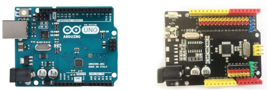
The most commonly used is the Arduino UNO control board. Below, we will take the Arduino UNO development board as an example (as shown in Figure 1) to learn together!
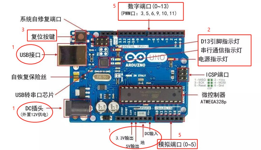
Figure 1
1. Power (Power) (as shown in Figures 2 and 3)
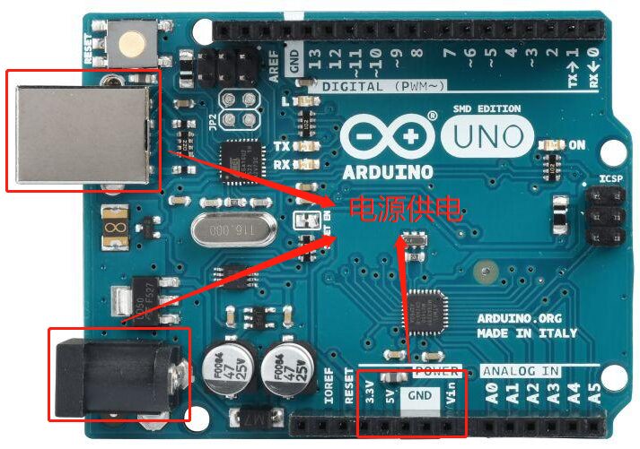
Figure 2
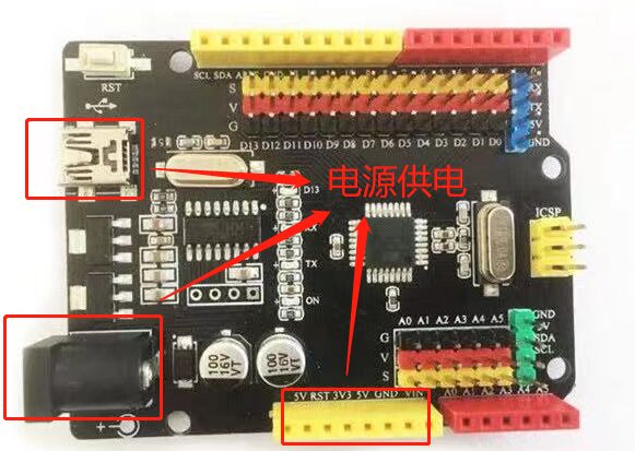
Figure 3
Arduino UNO has three power supply methods:
(1) Powered through the USB interface, voltage is 5V;
(2) Powered through the DC power input interface, voltage requirement is 7~12V;
(3) Powered through the power interface at 5V or VIN port, power supply at 5V port must be 5V, VIN port power supply is 7~12V.
2. Indicator Lights (LED) (as shown in Figures 4 and 5)
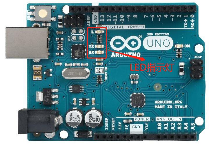
Figure 4

Figure 5
Arduino UNO has 4 LED indicator lights, which serve the following functions:
(1) ON, power indicator light. When Arduino is powered on, the ON light will illuminate.
(2) TX, serial transmission indicator light. When connected to a computer via USB and Arduino transmits data to the computer, the TX light will illuminate.
(3) RX, serial reception indicator light. When connected to a computer via USB and Arduino receives data from the computer, the RX light will illuminate.
(4) L, programmable control indicator light. This LED is connected to pin 13 of the Arduino through a special circuit. When pin 13 is high or in a high-impedance state, this LED will illuminate; when it is low, it will not illuminate. Therefore, this LED can be controlled by a program or external input signal.
3. Reset Button (Reset Button) (as shown in Figures 6 and 7)
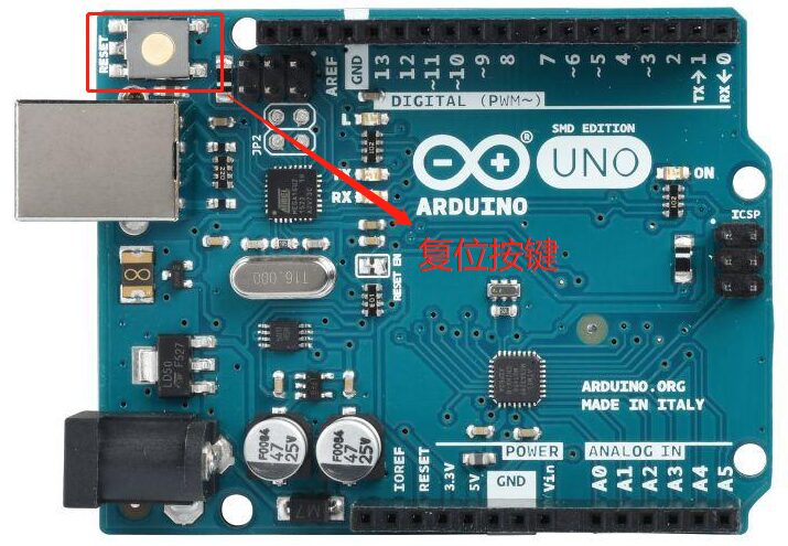
Figure 6
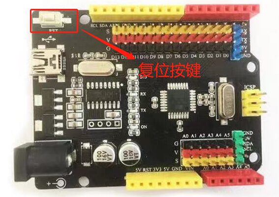
Figure 7
Pressing this button will restart the Arduino and begin executing the program from the start.
4. Memory (Memory)
The memory of Arduino is the storage space integrated into its main control chip. It can also be expanded by using peripheral chips. The memory of Arduino UNO is divided into three types:
(1) Flash, with a capacity of 32KB. Of this, 0.5KB is used as the BOOT area for storing the boot program, enabling the function of downloading programs via serial port; the remaining 31.5KB is for user storage. Compared to hard drives that can easily reach hundreds of GB today, 32KB may seem small, but for a microcontroller, 32KB can store a significant amount of programs.
(2) SRAM, with a capacity of 2KB. SRAM is equivalent to a computer’s memory, where the CPU needs to allocate storage space during calculations. Data in SRAM will be lost when the Arduino is powered off or reset.
(3) FEPROM, with a capacity of 1KB. FEPROM stands for Electrically Erasable Programmable Read-Only Memory, which is a type of read-only memory that can be modified by the user. Its characteristic is that data will not be lost when the Arduino is powered off or reset.
5. Input/Output Ports (Input/Output Port) (as shown in Figures 8 and 9)
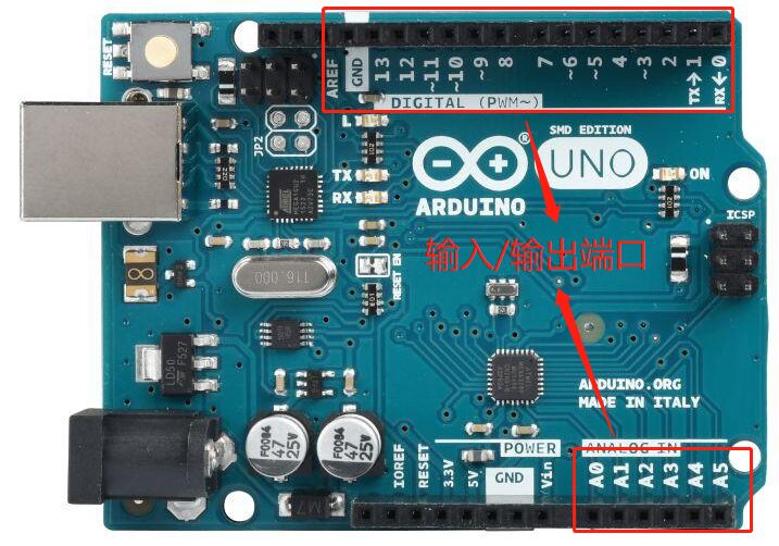
Figure 8
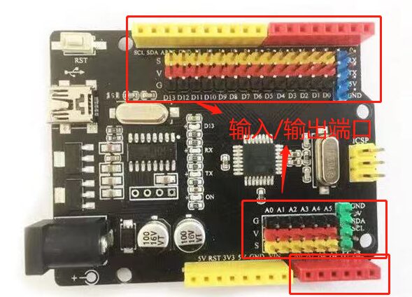
Figure 9
Arduino UNO has 14 digital input/output ports and 6 analog input ports. Some of these have special functions, as follows:
(1) UART communication, for pins 0 (RX) and 1 (TX), used for receiving and sending serial data. These two pins communicate with the computer via serial communication through the microcontroller (ATmega328P).
(2) External interrupt, for pins 2 and 3, can receive external interrupt signals.
(3) PWM output, for pins 3, 5, 6, 9, 10, and 11, can be used to output PWM waves.
(4) SPI communication, for pins 10 (SS), 11 (MOSI), 12 (MISO), and 13 (SCK), can be used for SPI communication.
(5) TWI communication, for pins A4 (SDA) and A5 (SCL), compatible with IIC communication.
(6) AREF, the input port for analog input reference voltage.
(7) Reset, the reset port. Connecting it to a low level will reset the Arduino. When the reset button is pressed, this port will be connected to a low level, thus resetting the Arduino.