If you don’t want to miss my updates, remember to check the official account in the upper right corner and set it as a star, take down the star and send it to me.


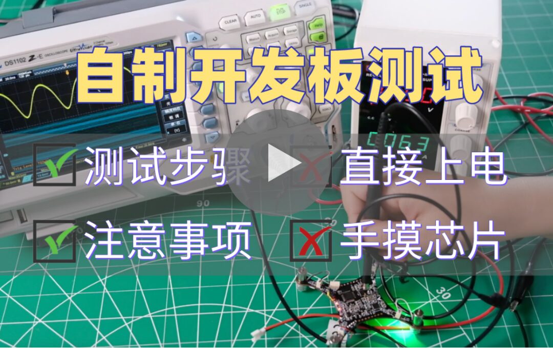
Hardware testing is a very important method for measuring the performance of the circuits designed by engineers, and it also relates to whether the product can work normally. For testing homemade boards and purchased development boards, in the sixth lesson of the fourth season Back2School, Ni Jie and Zhang Ze explained the testing steps in detail:
Most hardware tests can be seen as a model composed of three parts: input excitation, the object under test, and output response. Different testing methods are used for different tests. For development boards or our DIY boards, power testing should be done first, followed by functional testing, performance tuning, and some stability tests, while considering where the product will be used to conduct some reliability verifications, such as electrostatic discharge, high and low temperature, EMC, EMI, etc.
Special Board Benefits:
This season’s Back2School has prepared boards to assist everyone in transitioning from student to engineer positions.
How to obtain: Invite friends to follow the official WeChat of Jie Electronics (it must be followed using the QR code below, otherwise it cannot be counted).

Also receive 60 copies of C language books
Send the screenshot of friends’ follows and nicknames to Ni Jie for confirmation (WeChat: 459888529).
Invite 40 people to receive a 400 yuan+ Zhi Hui Quark development board; invite 20 people to receive a 200 yuan GROVE BEGINNER KIT; invite 10 people to receive a 150 yuan+ portable magnifier or custom umbrella.
Note: The list review and prize distribution will be conducted in November.
We have quite a few homemade development boards. Next, let’s take Xian‘s Little Ma Ge quadcopter as an example to highlight the testing processes:
When receiving the empty PCB board, the first thing is to visually inspect it to see if there are any obvious scratches or bumps on the edges. The reason for checking these two points is to prevent damage to the board during transportation, such as short circuits or broken lines.
In addition to visual inspection, it is also necessary to use a multimeter to measure the impedance between the power supply and ground to prevent any bumps during transportation that could cause a short circuit between the inner layers and the top or bottom layers.
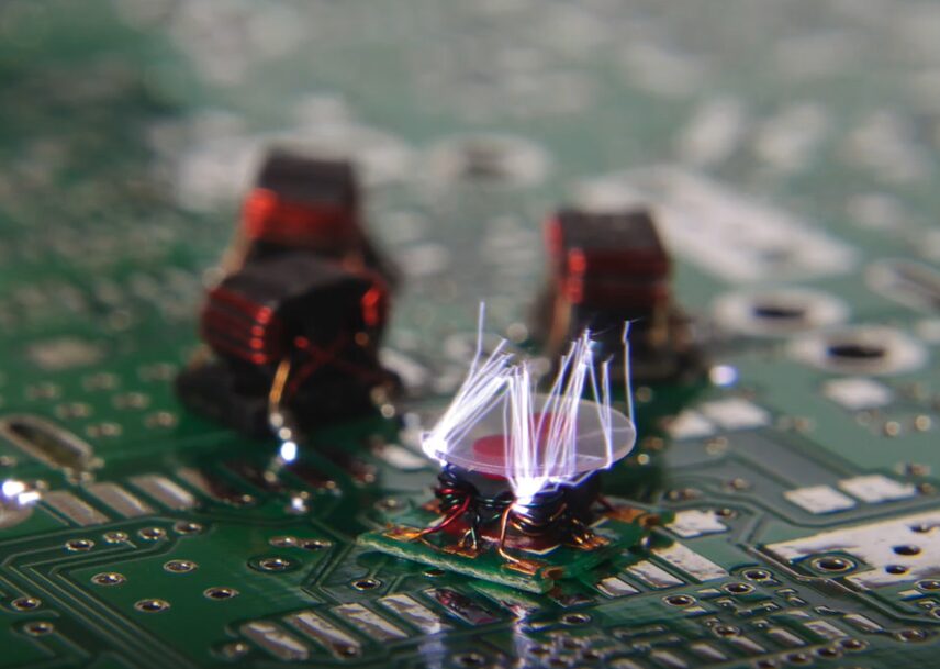
✔ Soldering
This quadcopter mainly consists of surface mount components, making soldering relatively simple. You can refer to the previous soldering tutorial: On the Importance of Soldering Tools! Summary of 12 Common Tools/Surface Mount Soldering.
✔ Visual Inspection Again
After soldering is completed, do not rush to power it on; there are several steps that must be taken:
Visual Inspection Again: After soldering, inspect again to prevent solder debris from remaining on the board, which could lead to PCB short circuits.

Soldering Condition: Check if the soldering is firm, and whether there are any cold solder joints or missed soldering.
Polarized Components: Check if polarized components that are prone to incorrect soldering, such as diodes, transistors, MOSFETs, etc., are soldered correctly.
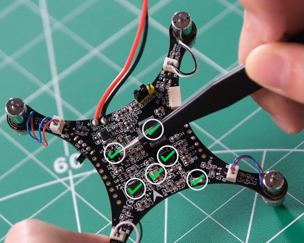
Wiring Order: Check the wiring of connectors based on the schematic, PCB, and the actual interface wiring of the board.
✔ Power-On Test
When powering on the board for the first time, it is recommended to use a regulated power supply. After setting the output voltage and current limit of the regulated power supply, proceed to power it on.
During power-on, it is essential to observe the current changes on the regulated power supply. If the current overloads, power off immediately. Not only in the case of triggering the current limit, but also if the current significantly exceeds the expected value for the board when stable, power off immediately and conduct further checks.
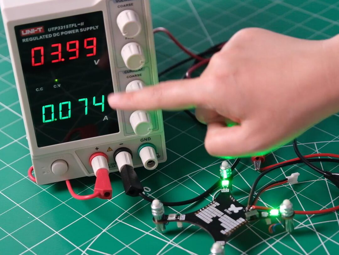
If the current is normal, further check the temperature on the board, especially for components with larger loads, such as motors or high-power SOCs, or other devices. Using temperature measurement devices, observe the temperature changes after the board stabilizes for a minute or two.
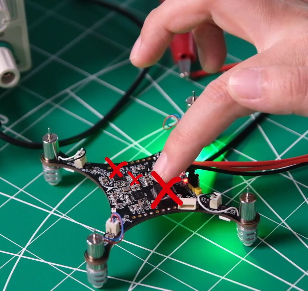
If there are no professional temperature measurement instruments, remember not to touch the components with your hands, especially in dry winter when your hands may carry static electricity, which could directly introduce static into the system. In addition, some circuits like DCDC, LDO, or operational amplifiers and clock circuits have feedback; touching the feedback pins with your hands could affect the output. Because it is a closed-loop adjustment, it could influence the output and potentially burn out the subsequent circuit or cause it to malfunction.
✔ Power Supply Test
First, test the power supply input to check the power-on waveform, noise, etc. This is to prevent external power supply noise from affecting the power supply of the board. When the board has issues, external power supply influence can be ruled out first.
Secondly, conduct internal power supply testing on the board, testing the power supply’s accuracy, noise, ripple, and so on. It is actually based on the power supply chip on the board to measure the output power supply situation level by level. If the subsequent circuit may have different requirements, such as power-on sequence for SOCs and FPGAs, use an oscilloscope to check the power-on sequence to see if it meets the system circuit requirements. If the power-on timing requirements are not met, the power consumption may increase several times during startup, potentially preventing the system from starting.
If the power supply test appears normal but the board still does not work, it may be that certain circuits have high accuracy requirements, and a better multimeter should be used to test the power supply circuit’s accuracy. It may also be that the subsequent circuit is sensitive and has noise requirements for the power supply, so check the noise. This noise could be the output noise of the LDO or the ripple caused by switching.
When testing the power supply, I generally test without load first. After confirming there are no issues, I will conduct load tests, including normal load ranges and overload conditions. In each test, pay attention to the dynamic situation. For example, what is the transient situation when jumping from zero load to a normal load, or from no load to heavy load, is very important. Especially for SOCs, FPGAs, DSPs, or heterogeneous devices, the kernel may exceed a very large transient current during startup. In addition, if controlling motors, power supplies, or heating devices, the instantaneous startup also has requirements; check whether the power supply circuit’s adjustment rate can meet the requirements and whether there is overshoot, and how the power supply loop performs. Many situations can arise, such as appearing normal without load but failing to work correctly under load.
Special Board Benefits:
This season’s Back2School has prepared boards to assist everyone in transitioning from student to engineer positions.
How to obtain: Invite friends to follow the official WeChat of Jie Electronics (it must be followed using the QR code below, otherwise it cannot be counted).

Scan to receive 60 copies of C language books.
Send the screenshot of friends’ follows and nicknames to Ni Jie for confirmation (WeChat: 459888529).
Invite 40 people to receive a 400 yuan+ Zhi Hui Quark development board; invite 20 people to receive a 200 yuan GROVE BEGINNER KIT ; invite 10 people to receive a 150 yuan+ portable magnifier or custom umbrella.
Note: The list review and prize distribution will be conducted in November.
If the board with the microcontroller has been soldered, powered on, and tested without issues, you can try connecting the microcontroller. The little quadcopter uses the STM32 microcontroller, which we have previously explained in C language programming; feel free to review and learn.
For the first operation of the microcontroller, you can try a simple demo test like turning on a light.
When the microcontroller does not work, you can check the following three items:
Step 1: Check Reset
Check several points for reset: First, check whether the reset level is correct, whether it is high-level reset or low-level reset, and whether it matches the design and chip requirements; second, check whether the reset time meets the requirements, such as the reset curve from 0 to 3.3V, ensuring the accurate reset time meets the microcontroller’s requirements.
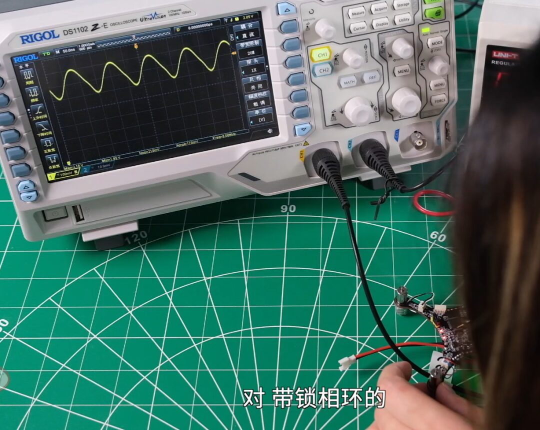
Step 2: Check Clock Circuit
Whether active, passive, or with a phase-locked loop, check whether the clock output is normal. For phase-locked loop circuits, check if it is locked.
Step 3: Check Startup Circuit
If using a microcontroller, a larger FPGA, or SOC, there are many driving modes. For instance, check whether the configuration pins are designed correctly and whether the pull-up and pull-down resistors are properly soldered. If using external configuration circuits, such as FLASH or SD, confirm whether the external circuit is correct.
If after checking these three steps the board still does not work, you need to go back to the schematic design to see if there are any design issues. If the board appears normal without load but becomes abnormal after programming, it is possible that the power supply testing was not done adequately. The core power supply may seem fine under no load or light load but fails when load is applied; this could be due to the microcontroller’s power supply traces being too thin to handle large currents. All these need to be revisited for supplementary testing.
✔ Software and Hardware Debugging
If the microcontroller program can be uploaded, it means that it can control various peripherals. For this quadcopter, it can operate sensors and control motors.
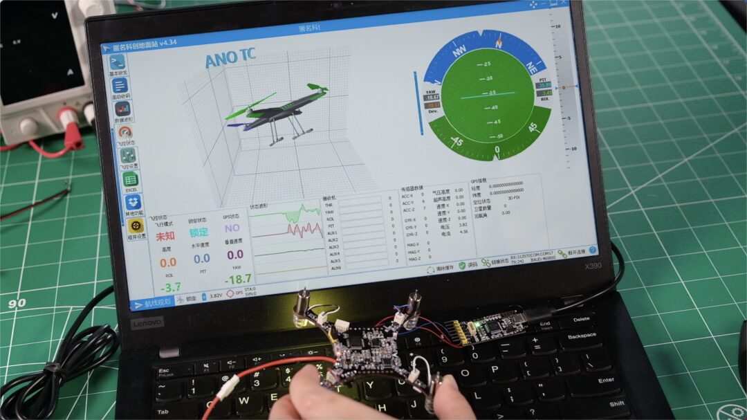
If it’s more digital, you can test each functional block path by path; if it’s more analog, you should follow the signal chain, such as DAC outputting a signal source, then adjusting through the first, second, third, and fourth stages.
In summary, different testing methods and paths should be used for different boards to complete overall functional testing and signal testing.
For purchased development boards, hardware testing after receiving them is relatively simple compared to homemade boards. After receiving the board, first check the completeness of the kit according to the list. For example, the Grove Beginner Kit includes the main board, tilt switch, buzzer, temperature and humidity sensor, three-axis digital accelerometer, light sensor, line follower, RGB LED, and LCD.
After confirming the device list is correct, you can test the main board and various functional modules according to the User Guides.
There are many contents related to hardware testing for homemade and purchased boards. There is a specialized direction and discipline that introduces considerations for testing during the design phase, namely design for testability. If interested, students can explore this further.

Fourth Season Back2School Content:
Introduction: Graduation Supply Station | 14 classes to assist in postgraduate entrance exams/job hunting/entrepreneurship, 3 major choices for you to pick.
Lesson 1: What can electronic majors do? Summary of trending industries/jobs/domestic companies.
Lesson 3: Key Points! How to read hundreds of pages of datasheets?
Lesson 4: On the Importance of Soldering Tools! Summary of 12 common tools/surface mount soldering.
Lesson 5: C language learning guide to prevent dropouts, with 60 e-books included.
Previous Back2School Content:
Season 1: Graduation Design “Guaranteed Pass” Secrets, with free boards included.
Season 2: 14 most memorable university projects to help you B2S.
Season 3: Electronic learning route guide: Practical! 16 sessions of [custom courses] for you to check.
2022 Back2School
The 4th season of Back2School starts from three choices (offers) of job hunting, postgraduate entrance exams, and entrepreneurship, providing the most comprehensive guidance for electronic major students.
Starting September 20, every Tuesday and Thursday at 20:00, the 4th season of Back2School will launch 12 online courses, 1 live class, and 1 offline workshop on Bilibili’s Darwin and Jie Electronics. Search on Bilibili for [Darwin] [Jie Electronics] to start learning.
60 copies of C language books, course-related materials, job hunting written test questions, and postgraduate review materials will be updated with the courses; you can scan to follow and receive:

Project Sharing | Electronic Competition Series | Artificial Intelligence | Postgraduate Entrance Exam
Essential Knowledge Points | Graduation Design | Switching Power Supply | Job Hunting
We are Ni Mo, the founder of Darwin, a sister who only talks about technology and not flirting. Darwin is an online education platform aimed at serving professionals in the electronics industry, providing skill training videos covering popular topics in various subfields, such as embedded systems, FPGA, artificial intelligence, etc., and tailoring layered learning content for different groups, such as common knowledge points, disassembly assessments, electronic competitions/intelligent vehicles/postgraduate entrance exams, etc. Welcome to follow.