When using PLCs, you will encounter many communication protocols and communication interfaces.
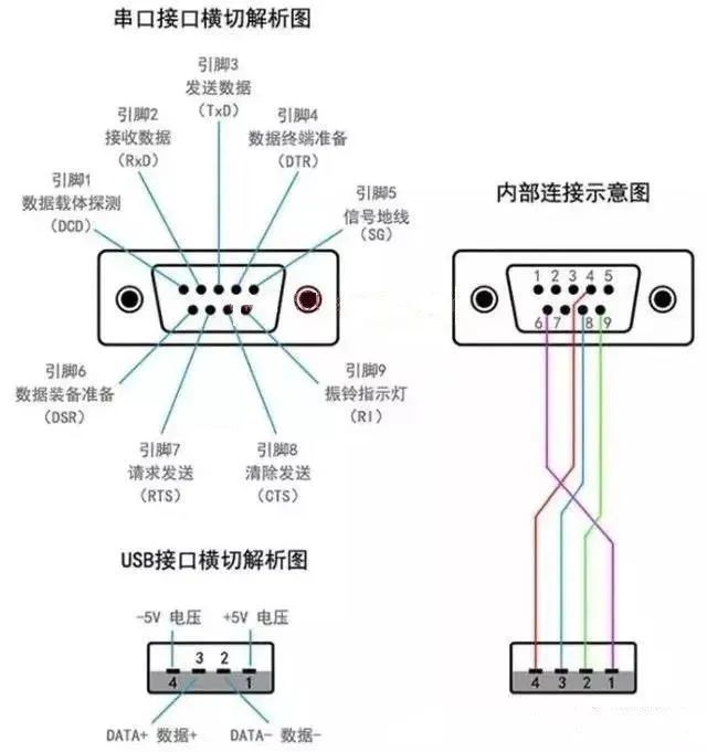
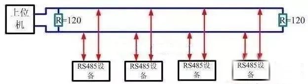
01What Is Serial Communication?A serial port is a very common device communication protocol on computers (do not confuse it with Universal Serial Bus or USB). Most computers have two RS232-based serial ports. The serial port is also a common communication protocol for instrument and meter devices; many GPIB-compatible devices also come with RS-232 ports. Additionally, the serial communication protocol can be used to retrieve data from remote collection devices.02Usage of Serial CommunicationSerial communication is completed using three wires: (1) Ground, (2) Transmit, (3) Receive. Since serial communication is asynchronous, the port can send data on one line while receiving data on another. Other lines are used for handshaking but are not mandatory.The most important parameters of serial communication are baud rate, data bits, stop bits, and parity. For two communicating ports, these parameters must match:a. Baud Rate: This is a parameter that measures communication speed. It indicates the number of bits transmitted per second. For example, 300 baud means 300 bits are sent per second. When we refer to clock cycles, we mean baud rate; for example, if the protocol requires a baud rate of 4800, then the clock is 4800Hz.This means that the sampling rate on the data line for serial communication is 4800Hz. Typically, the baud rates for telephone lines are 14400, 28800, and 36600. Baud rates can be much higher than these values, but baud rate is inversely proportional to distance. High baud rates are often used for devices that are placed very close together.b. Data Bits: This is a parameter that measures the actual data bits in communication. When a computer sends a packet, the actual data may not be 8 bits; the standard values are 5, 7, and 8 bits. How it is set depends on the information you want to transmit.For example, the standard ASCII code is 0–127 (7 bits). The extended ASCII code is 0–255 (8 bits). If the data uses simple text (standard ASCII code), then each data packet uses 7 bits of data. Each packet refers to a byte, including start/stop bits, data bits, and parity bits. Since the actual data bits depend on the selected communication protocol, the term “packet” refers to any communication case.c. Stop Bits: Used to indicate the last bit of a single packet. Typical values are 1, 1.5, and 2 bits. Since data is timed on the transmission line, and each device has its own clock, there may be slight desynchronization between the two devices during communication. Therefore, stop bits not only indicate the end of transmission but also provide an opportunity for the computer to correct clock synchronization. The more stop bits used, the greater the tolerance for clock synchronization differences, but the data transmission rate also slows down.d. Parity Bit: A simple error detection method in serial communication. There are four types of error detection: even, odd, high, and low. Of course, having no parity bit is also acceptable. In the case of even and odd parity, the serial port will set a parity bit (one bit after the data bits) to ensure that the transmitted data has an even or odd number of logical high bits.For example, if the data is 011, then for even parity, the parity bit is 0, ensuring that the number of logical high bits is even. If it is odd parity, the parity bit is 1, which results in three logical high bits. High and low bits do not actually check the data; they simply set the logical high or low for checking. This allows the receiving device to know the state of a bit and have the opportunity to determine whether noise has interfered with communication or if the transmitted and received data are out of sync.03Common PLC Basic Interfacesa. What Is RS-232?RS-232 (ANSI/EIA-232 standard) is the serial connection standard for IBM-PC and compatible machines. It can be used for many purposes, such as connecting a mouse, printer, or modem, and can also connect industrial instruments and meters. In practical applications, the transmission length or speed of RS-232 often exceeds the standard values.RS-232 is limited to point-to-point communication between PC serial ports and devices. The maximum distance for RS-232 serial communication is 50 feet.b. What Is RS-422?RS-422 (EIA RS-422-A standard) is the serial connection standard for Apple’s Macintosh computers.RS-422 uses differential signaling, while RS-232 uses unbalanced reference ground signals. Differential transmission uses two wires to send and receive signals, which provides better noise immunity and longer transmission distances compared to RS-232. In industrial environments, better noise immunity and longer transmission distances are significant advantages.c. What Is RS-485?RS-485 (EIA-485 standard) is an improvement over RS-422, as it increases the number of devices from 10 to 32, while defining the electrical characteristics under maximum device numbers to ensure sufficient signal voltage.With the capability for multiple devices, you can establish a device network using a single RS-422 port. Excellent noise resistance and multi-device capability make serial connections using RS-485 a choice for establishing distributed device networks connected to PCs, other data collection controllers, HMIs, or other operations in industrial applications.RS-485 is a superset of RS-422, so all RS-422 devices can be controlled by RS-485. RS-485 can perform serial communication over lines longer than 4000 feet.04Serial Communication1. SPI Transmission▲ Figure 1 SPI Data Transmission▲ Figure 1.2 SPI Data Transmission (2)▲ Figure 1.3 SPI Timing Signals
2. I2C Transmission
▲ Figure 1.2.1 I2C Bus and Addressing Method
3. UART Transmission
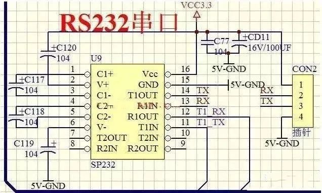
▲ Figure 1.3.1 Debugging MCU via UART on PC▲ Figure 1.3.2 RS-232 Communication with MCU via Level Conversion Chip
4. Infrared Control
▲ Figure 1.4.1 Infrared Control Signal is Also a Serial Communication Signal▲ Figure 1.4.2 Infrared Signal Reception and Amplification Shaping Circuit▲ Figure 1.4.3 A Circuit for Feeding Fish Using Infrared Receiver to Control Relay
5. Serial to Parallel Conversion Circuit
▲ Figure 1.5.1 Serial In, Parallel Out Shift Register▲ Figure 1.5.2 Shift Register Composed of Eight D Registers▲ Figure 1.5.4 Serial Transmission Schematic