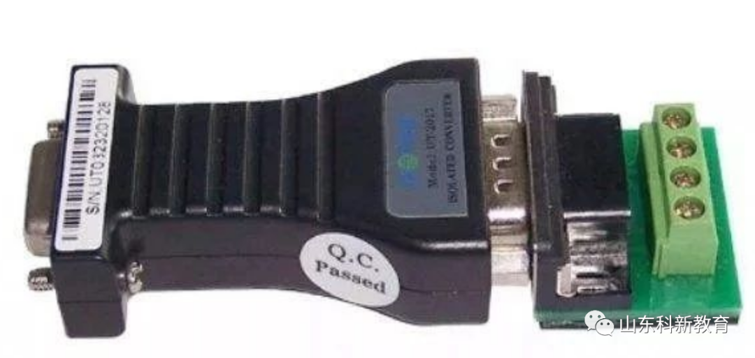
RS485 interfaces form a half-duplex network, typically using a two-wire system, often employing shielded twisted pairs for transmission. This wiring method allows a maximum of 32 nodes to be connected on the same bus topology. Initially, data was output as analog signals for simple process quantities, and the RS232 interface was used for instrument connections, enabling point-to-point communication. However, this method could not achieve networking capabilities, which was addressed by the emergence of RS485. This article provides a detailed introduction to the RS485 interface through a Q&A format.

1. What is the RS-485 Interface? What are its Characteristics Compared to RS-232-C?
Answer: Since the RS-232-C interface standard was introduced early on, it inevitably has some shortcomings, primarily including the following four points:
(1) The signal voltage levels of the interface are relatively high, which can damage the chips in the interface circuits. Additionally, because it is incompatible with TTL levels, level conversion circuits are required to connect to TTL circuits.
(2) The transmission rate is relatively low, with a baud rate of 20Kbps during asynchronous transmission.
(3) The interface uses one signal line and one signal return line, forming a common-ground transmission method. This common-ground transmission is susceptible to common-mode interference, resulting in poor noise immunity.
(4) The transmission distance is limited, with a maximum standard transmission distance of 50 feet, and in practice, it can only be used up to about 50 meters. To address the shortcomings of RS-232-C, new interface standards have continually emerged, among which RS-485 is one. It has the following characteristics:
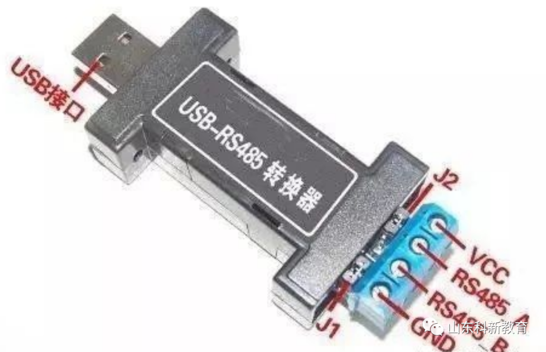
1) The electrical characteristics of RS-485: A logic “1” is represented by a voltage difference of + (2-6)V between the two wires; a logic “0” is represented by a voltage difference of – (2-6)V. The signal voltage levels of the interface are lower than those of RS-232-C, making it less likely to damage the chips in the interface circuits, and this level is compatible with TTL levels, facilitating connections to TTL circuits.
2) The maximum data transmission rate of RS-485 is 10Mbps.
3) The RS-485 interface employs a combination of balanced drivers and differential receivers, enhancing common-mode rejection, thus providing good noise immunity.
4) The maximum standard transmission distance of the RS-485 interface is 4000 feet, practically reaching up to 3000 meters. Additionally, while the RS-232-C interface allows only one transceiver on the bus, the RS-485 interface allows connection of up to 128 transceivers, enabling multi-station capabilities, allowing users to easily establish a device network using a single RS-485 interface.
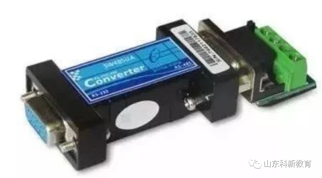
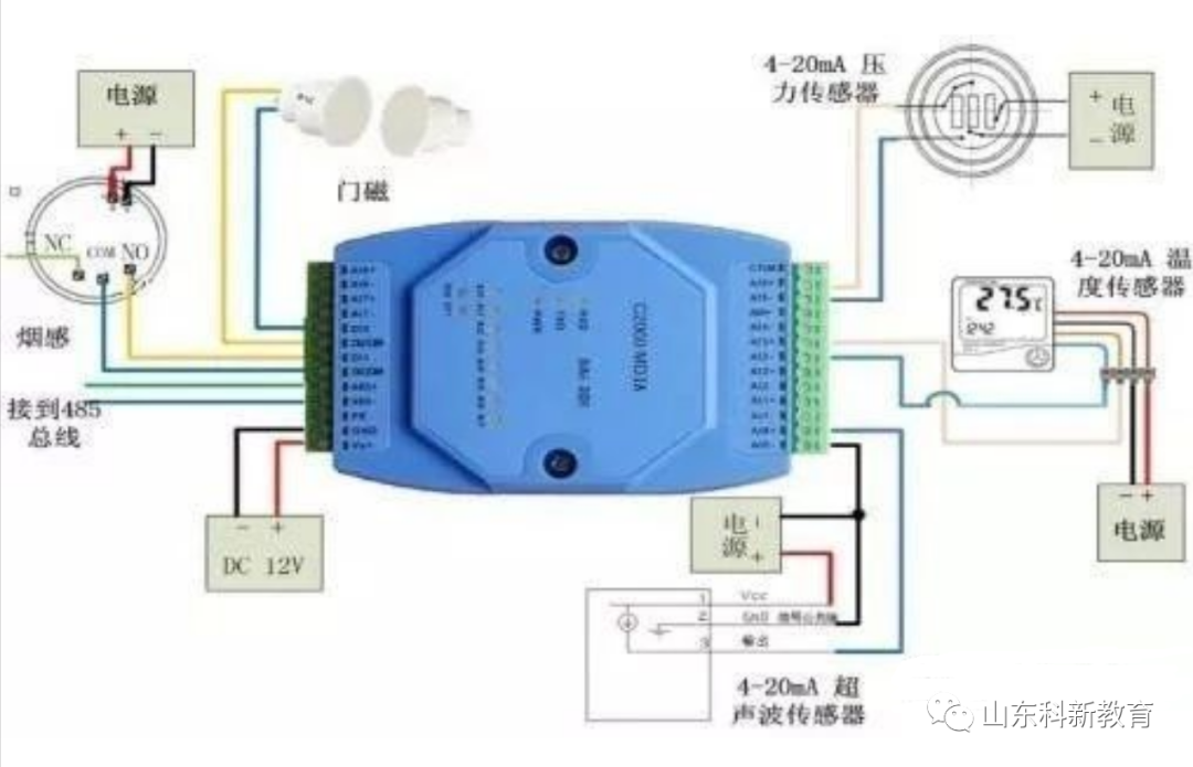
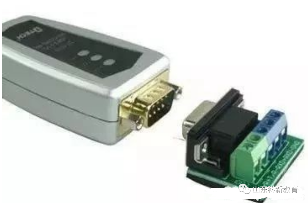
5) Due to the excellent noise immunity, long transmission distances, and multi-station capabilities of the RS-485 interface, it has become the preferred serial interface. The RS485 interface typically requires only two wires for the half-duplex network, and thus uses shielded twisted pairs for transmission. The RS485 connector uses a DB-9 9-pin plug, which connects to the intelligent terminal’s RS485 interface via a DB-9 (socket), and the keyboard connection uses a DB-9 (pin).
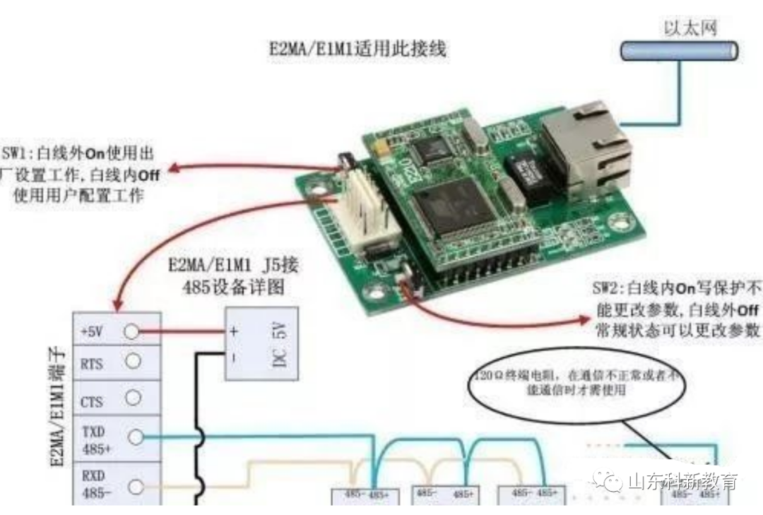
2. RS-422 and RS-485 Serial Interface Standards
1. Balanced Transmission
Unlike RS-232, RS-422 and RS-485 use differential transmission methods, also known as balanced transmission, utilizing a pair of twisted wires, defining one wire as A and the other as B.
Typically, the positive level between the sending drivers A and B is +2 to +6V, representing one logic state, and the negative level is -2 to 6V, representing another logic state. There is also a signal ground C, and in RS-485, there is an “enable” terminal, which is optional in RS-422. The “enable” terminal is used to control the connection and disconnection of the sending driver and transmission line. When the “enable” terminal is active, the sending driver is in a high-impedance state, known as the “third state,” which is distinct from logic “1” and “0.”
The receiver is also defined relative to the sending end; the receiving and sending ends are connected via the balanced twisted pairs AA and BB. When the voltage between AB at the receiving end exceeds +200mV, it outputs a positive logic level; when it is less than -200mV, it outputs a negative logic level. The range of voltages the receiver accepts on the balanced line is typically between 200mV and 6V.
2. RS-422 Electrical Specifications
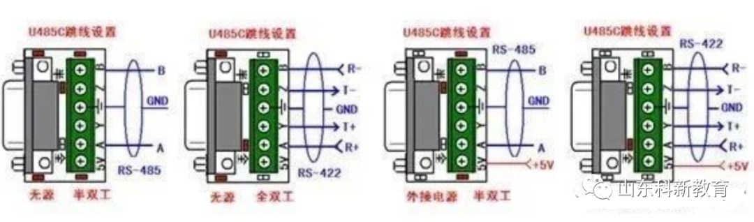
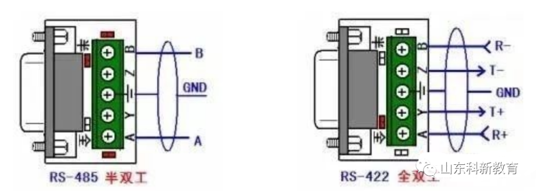
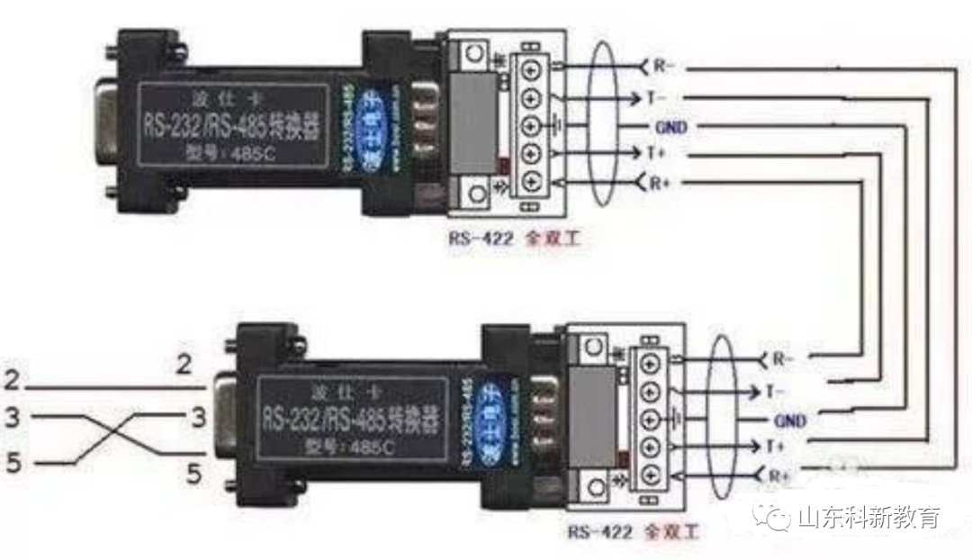
The full name of the RS-422 standard is “Electrical Characteristics of Balanced Voltage Digital Interface Circuits,” which defines the characteristics of the interface circuit. Figure 2 shows a typical RS-422 four-wire interface. In practice, there is also a signal ground wire, making a total of five wires. Figure 1 defines the pin assignments of its DB9 connector. Because the receiver uses high input impedance and stronger driving capability than RS232, multiple receiving nodes can be connected on the same transmission line, with a maximum of 10 nodes. This means one master device and the rest as slave devices, with no communication between slave devices, allowing RS-422 to support point-to-multipoint bidirectional communication. The input impedance of the receiver is 4k, so the maximum load capability of the sender is 10×4k + 100Ω (termination resistance). The RS-422 four-wire interface does not require controlling data direction, as any necessary signal exchange between devices can be implemented via software (XON/XOFF handshake) or hardware (a pair of separate twisted wires). The maximum transmission distance for RS-422 is 4000 feet (about 1219 meters), and the maximum transmission rate is 10Mb/s. The length of the balanced twisted pair is inversely proportional to the transmission rate; the maximum transmission distance can only be achieved at rates below 100kb/s. The highest transmission rates can only be achieved over very short distances. Generally, the maximum transmission rate on a 100-meter twisted pair is only 1Mb/s.
RS-422 requires a termination resistor, which should have a value approximately equal to the characteristic impedance of the transmission cable. Termination resistors are not needed for short-distance transmissions, typically below 300 meters. Termination resistors are connected at the far end of the transmission cable.
3. RS-485 Electrical Specifications
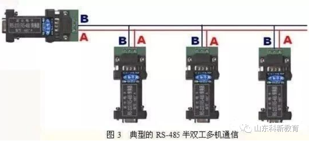
Since RS-485 is developed based on RS-422, many of its electrical specifications are similar to those of RS-422, such as using balanced transmission and requiring termination resistors on the transmission line. RS-485 can utilize two-wire and four-wire configurations; the two-wire system can achieve true multipoint bidirectional communication.
In a four-wire configuration, similar to RS-422, only point-to-multipoint communication can be achieved, with one master device and the rest as slave devices, but with improvements over RS-422, allowing up to 32 devices to be connected on the bus regardless of whether it is a four-wire or two-wire configuration.
RS-485 differs from RS-422 in that its common-mode output voltage ranges differ, with RS-485 ranging from -7V to +12V, while RS-422 ranges from -7V to +7V. The minimum input impedance for RS-485 receivers is 12k, while for RS-422, it is 4k. RS-485 can meet all RS-422 specifications, allowing RS-485 drivers to be used in RS-422 networks.
Both RS-485 and RS-422 have a maximum transmission distance of approximately 1219 meters and a maximum transmission rate of 10Mb/s. The length of the balanced twisted pair is inversely proportional to the transmission rate; the maximum cable length can only be used at rates below 100kb/s. Only at very short distances can the highest transmission rates be achieved. Typically, the maximum transmission rate on a 100-meter twisted pair is only 1Mb/s.
RS-485 requires two termination resistors, which should be equal to the characteristic impedance of the transmission cable. Termination resistors are not required for short-distance transmission, generally below 300 meters. Termination resistors are connected at both ends of the transmission bus.
3. Key Points for RS-422 and RS-485 Network Installation
RS-422 supports 10 nodes, while RS-485 supports 32 nodes, allowing for multi-node networks. The network topology typically employs a terminal-matching bus structure and does not support ring or star networks. When constructing a network, the following points should be noted:
1. Use a twisted pair cable as the bus to connect each node in series. The lead length from the bus to each node should be kept as short as possible to minimize the influence of reflected signals in the leads on the bus signals. The figure shows some common incorrect connection methods (a, c, e) and correct connection methods (b, d, f) in practical applications. Although the three incorrect network connections (a, c, e) may work correctly at short distances and low speeds, their adverse effects will become more pronounced with increased communication distances or speeds. The primary reason is that signals reflected at the ends of the branches overlap with the original signals, degrading signal quality.
2. Ensure continuity of the bus’s characteristic impedance; signal reflections occur at points of impedance discontinuity. The following situations are prone to such discontinuities: different cables used in different sections of the bus, too many transceivers installed closely together on one segment of the bus, or excessively long branch lines extending to the bus.
In summary, a single, continuous signal channel should be provided as the bus.
4. Some Explanations on Matching for RS-422 and RS-485 Transmission Lines
Termination resistors are generally required for matching RS-422 and RS-485 bus networks. However, for short distances and low speeds, matching can be disregarded. When is it unnecessary to consider matching? Theoretically, when sampling the midpoint of each receiving data signal, as long as the reflected signal decays to a sufficiently low level before sampling begins, matching can be ignored. However, this is difficult to manage in practice. An article from Maxim in the USA mentions an empirical rule for determining when matching is necessary based on data rates and cable lengths: when the signal transition time (rise or fall time) exceeds three times the time it takes for the electrical signal to travel one way along the bus, matching can be ignored. For example, the MAX483 RS-485 interface has a minimum rise or fall time of 250ns, and the typical transmission rate on twisted pair cable is about 0.2m/ns (24AWG PVC cable). Therefore, as long as the data rate is below 250kb/s and the cable length does not exceed 16 meters, the MAX483 can be used as an RS-485 interface without termination matching.
Generally, termination matching uses termination resistors, as mentioned earlier. RS-422 has termination resistors connected at the far end of the bus cable, while RS-485 requires termination resistors at both the start and end of the bus cable. Termination resistors are typically set at 100Ω for RS-422 networks and 120Ω for RS-485 networks, corresponding to the characteristic impedance of the cable, as most twisted pair cables have characteristic impedances of approximately 100-120Ω. This matching method is simple and effective but has a drawback: the matching resistors consume significant power, making it unsuitable for systems with strict power consumption limits.
Another more power-efficient matching method is RC matching, which uses a capacitor C to block the DC component to save most of the power. However, determining the value of capacitor C is challenging, as it requires a trade-off between power consumption and matching quality.
Another method uses diodes for matching. Although this method does not achieve true “matching,” it effectively uses the clamping action of diodes to quickly attenuate reflected signals, improving signal quality. The energy-saving effect is significant.
5. Grounding Issues for RS-422 and RS-485
Proper grounding of electronic systems is crucial but often overlooked. Improper grounding can lead to unstable operation of electronic systems and even jeopardize system safety. Grounding for RS-422 and RS-485 transmission networks is equally important, as an unreasonable grounding system can affect the stability of the entire network, especially in harsh working environments and over long distances, where grounding requirements are stricter. Otherwise, the interface damage rate is relatively high. In many cases, connecting RS-422 and RS-485 communication links is simply done by using a pair of twisted wires to connect the “A” and “B” ends of each interface. However, the connection of the signal ground is often neglected. This connection method may work normally in many cases, but it poses significant risks for the following two reasons:
1. Common-mode interference: As mentioned earlier, both RS-422 and RS-485 interfaces use differential methods for signal transmission, which do not require detection of signals relative to a reference point; the system only needs to detect the potential difference between the two wires. However, people often overlook that transceivers have a certain common-mode voltage range, such as -7 to +7V for RS-422 and -7 to +12V for RS-485. Only by meeting these conditions can the entire network operate normally. When the common-mode voltage exceeds this range within the network lines, it can affect the stability and reliability of communication, even damaging the interface. For example, when the sending driver A sends data to receiver B, the common-mode voltage output from sending driver A is VOS. Due to the independent grounding systems of the two systems, there is a ground potential difference VGPD. Therefore, the common-mode voltage at the receiver input can be expressed as VCM = VOS + VGPD. Both RS-422 and RS-485 standards specify that VOS ≤ 3V, but VGPD can vary greatly (tens of volts or even more), potentially accompanied by strong interference signals, causing the common-mode input VCM of the receiver to exceed the normal range and generating interference currents on the transmission line, which can disrupt normal communication or even damage the communication interface circuit.
2. EMI issues: The common-mode portion of the output signal from the sending driver requires a return path. If there is no low-resistance return channel (signal ground), it will return to the source in a radiated manner, causing the entire bus to act like a huge antenna radiating electromagnetic waves.
For these reasons, despite using differential balanced transmission methods, the entire RS-422 or RS-485 network must have a low-resistance signal ground. A low-resistance signal ground connects the working grounds of the two interfaces, allowing the common-mode interference voltage VGPD to be shorted out.
This signal ground can be an additional wire (non-shielded twisted pair) or the shielding layer of a shielded twisted pair. This is the most common grounding method.
It is worth noting that this method is only effective for high-impedance common-mode interference. Since the internal resistance of the interference source is large, shorting it will not create a significant ground loop current, thus having little impact on communication. When the internal resistance of the common-mode interference source is low, a large loop current may form on the grounding line, affecting normal communication. The author believes that three measures can be taken:
(1) If the internal resistance of the interference source is not very small, a current-limiting resistor can be added to the grounding line to limit the interference current. Increasing the grounding resistance may raise the common-mode voltage, but as long as it is controlled within an appropriate range, it will not affect normal communication.
(2) Floating ground technology can be used to cut off the grounding loop. This is a commonly used and very effective method. When the internal resistance of the common-mode interference is very low, the above methods may not work. In such cases, it may be considered to float the node introducing the interference (for example, field devices in harsh working environments), thereby isolating the grounding loop and preventing a large loop current from forming.
(3) Isolation interfaces can be used. In some cases, for safety or other reasons, the circuit ground must be connected to the chassis or earth and cannot be floated. In this case, isolation interfaces can be used to cut off the grounding loop, but there should still be a ground wire connecting the common terminal on the isolated side with the working ground of other interfaces.
6. Fault Protection for RS-422 and RS-485 Networks
Both RS-422 and RS-485 standards specify a receiver threshold of ±200mV. This specification provides relatively high noise suppression capability. As mentioned earlier, when the voltage level of receiver A exceeds that of receiver B by more than +200mV, it outputs a positive logic level; conversely, it outputs a negative logic level. However, due to the existence of the third state, when the host sends a data message and places the bus in the third state, meaning that there is no signal driving the bus during idle times, the voltage between A and B may drop to between -200mV and +200mV and approach 0V, leading to a problem where the receiver output state becomes uncertain. If the receiver output is 0V, slave devices in the network will interpret this as a new start bit and attempt to read subsequent bytes, which will never have a stop bit, resulting in frame errors and causing the network to become paralyzed without any devices requesting the bus. Besides the aforementioned idle state causing the voltage difference between the two wires to drop below 200mV, open or short circuits can also lead to this situation. Therefore, certain measures should be taken to avoid the receiver being in an uncertain state.
Usually, a bias is added to the bus, using bias resistors to keep the bus in a defined state (differential voltage ≥ -200mV) when the bus is idle or open. As shown in Figure 1, pulling A to ground and pulling B down to 5V, with typical resistor values of 1kΩ, can vary based on the capacitance of the cable.
The above method is a classic approach, but it still cannot solve the problem of bus short circuits. Some manufacturers have moved the receiver threshold to -200mV/-50mV to address this issue.
7. Transient Protection for RS-422 and RS-485
The signal grounding measures mentioned earlier only protect against low-frequency common-mode interference and are ineffective against high-frequency transient interference. Since transmission lines behave like inductors for high-frequency signals, the grounding line effectively becomes an open circuit for high-frequency transient interference. Although such transient interference lasts only a short time, it may involve hundreds or thousands of volts.
In practical application environments, the possibility of high-frequency transient interference still exists. Generally, switching large inductive loads, such as motors, transformers, and relays, or during lightning events, can generate high-amplitude transient interference. If not adequately protected, RS-422 or RS-485 communication interfaces may be damaged. To protect against such transient interference, isolation or bypass methods can be employed.
1. Isolation protection method. This scheme effectively transfers the transient high voltage to the isolation layer of the isolation interface. Due to the high insulation resistance of the isolation layer, it does not produce damaging surge currents, thus protecting the interface. Typically, high-frequency transformers, optocouplers, and other components are used to achieve electrical isolation of the interface. Some device manufacturers have integrated all these components into a single IC, making it very convenient to use. The advantage of this scheme is its ability to withstand high voltages and long-duration transient interference, and it is relatively easy to implement, but it has a higher cost.
2. Bypass protection method. This method uses transient suppression components (such as TVS, MOV, gas discharge tubes, etc.) to divert harmful transient energy to the ground. The advantage is lower cost, while the disadvantage is limited protection capability, only protecting against transient interference within a certain energy range and for a limited duration, and it requires a good connection to ground, making implementation more challenging. In practical applications, these two methods are often flexibly combined, as shown in Figure 1. In this method, the isolation interface isolates high-amplitude transient interference, while the bypass components protect the isolation interface from breakdown due to excessive transient voltage.
8. When Using RS485 Interfaces, How to Consider the Length of Transmission Cables?
When using RS485 interfaces, the maximum allowable cable length for specific transmission lines from the generator to the load is a function of the data signal transmission rate, primarily limited by signal distortion and noise. The relationship between maximum cable length and signal rate is derived from using 24AWG copper-core twisted telephone cables (diameter 0.51mm), with inter-wire bypass capacitance of 52.5PF/M, and a terminal load resistance of 100 ohms. When the data signal rate drops below 90Kbit/S, assuming a maximum allowable signal loss of 6dBV, the cable length is limited to 1200M. In practice, it is entirely possible to achieve greater cable lengths than this.
9. How to Achieve RS-485/422 Multipoint Communication
At any time on the RS-485 bus, there can only be one transmitter sending. In half-duplex mode, only one master can send. In full-duplex mode, the master can always transmit, while the slave can only have one sender.
10. Under What Conditions is Terminal Matching Required for RS-485/RS-422 Interfaces? How is the Resistance Value Determined? How to Configure Terminal Matching Resistors?
In long-line signal transmission, terminal matching resistors are generally required at the receiving end to avoid signal reflection and echoes. The value of the terminal matching resistor depends on the impedance characteristics of the cable and is independent of the cable length.
RS-485/RS-422 generally uses twisted pairs (shielded or unshielded) for connection. The terminal resistance typically ranges from 100 to 140Ω, with a typical value of 120Ω. In practical configuration, a termination resistor should be installed at both terminal nodes of the cable, at the nearest and farthest ends, while intermediate nodes should not have termination resistors connected, as this could lead to communication errors.
11. What to Do if the Farthest Node in an RS-485 Network is Unknown When Connecting Matching Resistors?
This situation arises when users do not adhere to the principle of keeping the wiring from the node to the bus as short as possible when forming the RS-485 network. If the bus wiring follows this principle, there should be no uncertainty about which node is the farthest. Moreover, it should be noted that such wiring will not work well.
12. Why Does the Receiver Still Output Data When RS-485/RS-422 Communication is Stopped?
Since RS-485/RS-422 requires that all sending enable control signals be turned off and the receiving enable remains active after data transmission is complete, the bus driver enters a high-impedance state, allowing the receiver to monitor whether new communication data is present on the bus. However, during this time, if the bus is in a passive driving state (if there are termination resistors on the bus, the differential level of wires A and B is 0, and the receiver output is uncertain; if there are no termination resistors, the bus is in high-impedance state, and the receiver output is uncertain), it is easily affected by external noise interference. When the noise voltage exceeds the input signal threshold (typical value ±200mV), the receiver will output data, causing the UART to receive invalid data, resulting in subsequent normal communication errors; another situation may occur during the moment of enabling/disabling the sending control, which may cause the receiver to output signals, leading to erroneous UART reception.
Solutions:
1) Use pull-up on the non-inverting input terminal (line A) and pull-down on the inverting input terminal (line B) to clamp the bus, ensuring the receiver output is fixed at a “1” level;
2) Replace the interface circuit with MAX308x series interface products that have built-in fault-tolerant modes;
3) Eliminate via software, adding 2-5 starting sync bytes within the communication data packet, only starting actual data communication once the sync header is satisfied.
13. Three Factors Affecting RS-485 Bus Communication Speed and Reliability
1. Signal Reflection in Communication Cables
During communication, signal reflections can occur due to two reasons: impedance discontinuities and mismatches. Impedance discontinuities cause signals to reflect when they encounter a much lower or no impedance at the end of the transmission line, similar to light reflecting when transitioning between media. To eliminate such reflections, a termination resistor equal to the characteristic impedance of the cable must be connected at the end of the cable. Since signals travel bidirectionally on the cable, a similar termination resistor can also be connected at the other end. Theoretically, as long as a termination resistor matching the cable’s characteristic impedance is connected at the end of the transmission cable, signal reflections should no longer occur. However, in practical applications, due to the characteristic impedance of the transmission cable being related to the communication baud rate and other environmental factors, it is unlikely that the characteristic impedance will match the termination resistor perfectly, thus some degree of signal reflection will still occur.
The other cause of signal reflection is the mismatch between the transceiver and the transmission cable impedance. This mismatch primarily manifests when the communication line is idle, causing data chaos throughout the network.
The impact of signal reflection on data transmission ultimately arises because the reflected signals trigger the comparator at the receiver’s input, causing the receiver to receive incorrect signals, leading to CRC check errors or entire data frame errors.
In signal analysis, the parameter used to measure the intensity of reflected signals is RAF (Reflection Attenuation Factor). Its calculation formula is as follows:
RAF = 20lg(Vref/Vinc)
Where: Vref is the voltage magnitude of the reflected signal; Vinc is the voltage magnitude of the incident signal at the connection point of the cable and transceiver or termination resistor.
Specific measurement methods are illustrated in Figure 3. For example, if the peak-to-peak value of a 2.5MHz incident signal sine wave is +5V, and the peak-to-peak value of the reflected signal is +0.297V, then the reflection attenuation factor for this communication cable at a 2.5MHz communication rate is: RAF = 20lg(0.297/2.5) = -24.52dB
To mitigate the impact of reflected signals on communication lines, noise suppression and bias resistors are typically employed. In practical applications, for relatively small reflected signals, the addition of bias resistors is often a simple and convenient method. The principle of how bias resistors improve communication reliability will be detailed later.
14. Signal Attenuation in Communication Cables
The second factor affecting signal transmission is the attenuation of signals during transmission through cables. A transmission cable can be viewed as an equivalent circuit composed of distributed capacitance, distributed inductance, and resistance.
The distributed capacitance C of the cable is primarily generated by the two parallel conductors of the twisted pair. The resistance of the conductors has a minimal impact on the signal and can be ignored. The signal loss is mainly due to the LC low-pass filter formed by the distributed capacitance and inductance of the cable. The attenuation coefficients of standard LAN-type two-core inductors used in PROFIBUS (the standard cable selected for Siemens’ DP bus) at different baud rates are shown.
15. Pure Resistive Loads in Communication Cables
The third factor affecting communication performance is the size of the pure resistive load (also known as DC load). This refers to the combination of termination resistors, bias resistors, and RS-485 transceivers.
As mentioned in the EIARS-485 specification, the RS-485 driver can output a minimum differential voltage of 1.5V when connected to 32 nodes with 150Ω termination resistance. The input resistance of one receiver is 12kΩ, and the equivalent circuit of the entire network is shown in Figure 5. Based on this calculation, the load capacity of the RS-485 driver is: RL = 32 input resistances in parallel || 2 termination resistances = ((12000/32) × (150/2)) / ((12000/32) + (150/2)) ≈ 51.7Ω.
Currently, commonly used RS-485 drivers include MAX485, DS3695, MAX1488/1489, and the SN75176A/D used by Holley, among others, some of which can handle load capacities of up to 20Ω. Ignoring other factors, based on the relationship between driving capability and load, a driver can support a maximum number of nodes far exceeding 32.
When communication baud rates are high, the addition of bias resistors on the lines is very necessary. The connection method for bias resistors is to pull the bus voltage away from 0V when the line is in an idle state (no data). This way, even if small reflected signals or interference occur in the line, the data receivers connected to the bus will not malfunction due to these signals. Through the following example, the size of the bias resistors can be calculated: termination resistors Rt1 = Rr2 = 120Ω;
Assuming the maximum peak-to-peak value of the reflected signal Vref ≤ 0.3Vp-p, then the negative half-cycle voltage Vref ≤ 0.15V; the reflected current Iref caused by the reflected signal on the termination resistor ≤ 0.15/(120||120) = 2.5mA. The typical hysteresis voltage value of most RS-485 transceivers (including SN75176) is 50mV, thus:
(Ibias – Iref) × (Rt1 || Rt2) ≥ 50mV
Therefore, it can be calculated that the bias current Ibias ≥ 3.33mA
+5V = Ibias (Rup + Rdown + (Rt1 || Rt2))
Through this equation, it can be calculated that Rup = Rdown = 720Ω.
In practical applications, there are two methods for adding bias resistors to the RS-485 bus:
(1) Distributing bias resistors evenly to each transceiver on the bus. This method adds a bias resistor to every transceiver connected to the RS-485 bus, providing a bias voltage to each transceiver.
(2) Using a pair of bias resistors on one segment of the bus. This method is particularly effective against large reflected signals or interference. It is worth noting that the addition of bias resistors increases the load on the bus.
16. The Relationship Between the Load Capacity of the RS-485 Bus and the Length of Communication Cables
When designing the network configuration of RS-485 buses (length and number of loads), three parameters should be considered: pure resistive load, signal attenuation, and noise margin. The pure resistive load and signal attenuation parameters have been discussed earlier; now we will discuss noise margin (Noise Margin). The noise margin of RS-485 bus receivers should be at least greater than 200mV. The previous discussions assumed a noise margin of 0.
In practical applications, to improve the bus’s anti-interference ability, it is hoped that the system’s noise margin is better than that specified in the EIARS-485 standard. The relationship between the number of loads on the bus and the length of communication cables can be seen from the following formula: Vend = 0.8(Vdriver – Vloss – Vnoise – Vbias)
Where: Vend is the signal voltage at the end of the bus, which is specified as 0.2V during standard measurement; Vdriver is the output voltage of the driver (related to the number of loads. When the number of loads is between 5 and 35, Vdriver = 2.4V; when the number of loads is less than 5, Vdriver = 2.5V; when the number of loads exceeds 35, Vdriver ≤ 2.3V); Vloss is the signal loss during transmission on the bus (related to the specifications and lengths of communication cables), based on the standard attenuation coefficient provided in Table 1, the attenuation coefficient can be calculated as b = 20lg(Vout/Vin), thus Vloss = Vin – Vout = 0.6V (Note: The communication baud rate is 9.6kbps, and the cable length is 1km; if the baud rate increases, Vloss will also increase); Vnoise is the noise margin, which is specified as 0.1V during standard measurement; Vbias is the bias voltage provided by the bias resistors (typical value is 0.4V).
Multiplying by 0.8 in this formula ensures that the communication cable does not enter a fully loaded state. From this equation, it can be seen that the size of Vdriver is inversely proportional to the number of loads on the bus, and Vloss is inversely proportional to the length of the bus; the other parameters depend only on the type of driver used. Therefore, once the driver for the RS-495 bus has been selected, under a fixed communication baud rate, the number of loads is directly related to the maximum distance that signals can be transmitted. The specific relationship is: within the allowable range of the bus, the more loads there are, the shorter the distance signals can be transmitted; the fewer loads there are, the farther the signals can be transmitted.
17. The Impact of Distributed Capacitance on RS-485 Bus Transmission Performance
The distributed capacitance of the cable is primarily generated by the two parallel conductors of the twisted pair. Additionally, there is also distributed capacitance between the conductors and the ground, which, although small, cannot be ignored in analysis. The impact of distributed capacitance on bus transmission performance primarily arises because the transmission on the bus involves baseband signals, which can only express “1” and “0.” In special bytes, such as 0x01, the signal “0” allows sufficient charging time for the distributed capacitance, while when the signal “1” arrives, the charge in the distributed capacitance cannot discharge in time, leading to (Vin+) – (Vin-) – still being greater than 200mV, causing the receiver to mistakenly interpret it as “0,” ultimately resulting in CRC check errors and incorrect transmission of the entire data frame.
Due to the impact of distributed capacitance, data transmission errors occur, leading to a reduction in overall network performance. There are two methods to resolve this issue:
(1) Lower the data transmission baud rate;
(2) Use cables with lower distributed capacitance to improve the quality of the transmission line.
18. Definitions of Simplex, Half-Duplex, and Full-Duplex
1. If at any time during communication, information can only be transmitted from one party A to another party B, it is termed simplex.
2. If at any time, information can be transmitted from A to B and also from B to A, but transmission can only exist in one direction, it is termed half-duplex transmission.
3. If at any time, there exist bidirectional signal transmissions from A to B and from B to A on the line, it is termed full-duplex.
Telephone lines are examples of two-wire full-duplex channels. By employing echo cancellation technology, bidirectional transmission signals do not become confused. Full-duplex channels sometimes also separate the receiving and transmitting channels, using separate lines or frequency bands to transmit signals in opposite directions, such as in loopback transmission.
Modbus Communication Protocol Explained
Introduction: The ModBus network is an industrial communication system formed by programmable controllers with intelligent terminals connected via public lines or local dedicated lines. Its system structure includes both hardware and software, and it can be applied to various data collection and process monitoring.
The Modbus network has only one master, and all communication is initiated by it. The network can support up to 247 remote slave controllers, but the actual number of slaves supported depends on the communication devices used. By using this system, each PC can exchange information with the central master without affecting its own control tasks.
Understanding the Modbus communication protocol allows for communication testing in the field using various third-party software.
The Modbus protocol includes ASCII, RTU, TCP, etc., and does not specify the physical layer. This protocol defines the message structure that controllers can recognize and use, regardless of the network through which they communicate. Standard Modicon controllers use RS232C to implement serial Modbus. The ASCII and RTU protocols of Modbus define the structure of messages, data, commands, and responses, with data communication adopting a Master/Slave mode, where the Master sends data request messages, and the Slave can send data back to the Master in response to the request; the Master can also directly send messages to modify data on the Slave, achieving bidirectional read and write.
The Modbus protocol requires data to be checked; in serial protocols, besides parity checks, the ASCII mode uses LRC checks, and the RTU mode uses 16-bit CRC checks, while the TCP mode does not have additional checks, as the TCP protocol is a reliable connection-oriented protocol. Additionally, Modbus adopts a master-slave timing mechanism for data transmission. In practical use, if a slave station disconnects (e.g., due to a fault or shutdown), the Master can diagnose it, and once the fault is repaired, the network can automatically reconnect. Therefore, the reliability of the Modbus protocol is relatively high.
For Modbus’s ASCII, RTU, and TCP protocols, TCP and RTU protocols are very similar; we just need to remove the two-byte checksum from the RTU protocol and add 5 zeros and a 6 at the start before sending it through the TCP/IP network protocol.
1. Communication Transmission Method:
Communication transmission is divided into independent information headers and encoded data sent. The following communication transmission method definitions are also compatible with the ModBus RTU communication protocol:
Initial Structure = ≥4 bytes of time
Address Code = 1 byte
Function Code = 1 byte
Data Area = N bytes
Error Check = 16-bit CRC code
End Structure = ≥4 bytes of time
Address Code: The address code is the first byte of the communication transmission. This byte indicates which slave with the user-set address will receive the information sent by the master. Each slave must have a unique address code, and responses must begin with their respective address codes. The address code sent by the master indicates which slave it is sending to, while the address code sent by the slave indicates the source of the returned information.
Function Code: The second byte of the communication transmission. The ModBus communication protocol defines function numbers from 1 to 127. This instrument only utilizes a portion of these function codes. As the master requests to send, it informs the slave what action to perform through the function code. As the slave responds, the function code sent by the slave matches that sent by the master, indicating that the slave has responded to the master’s operation. If the function code sent by the slave has the highest bit set to 1 (for example, function codes greater than 127), it indicates that the slave did not respond to the operation or an error occurred.
Data Area: The data area varies according to different function codes. It can be actual values, set points, or addresses sent from the master to the slave or from the slave to the master.
CRC Code: A two-byte error detection code.
2. Communication Protocol:
When communication commands are sent to the instrument, the device with the corresponding address code receives the command, removes the address code, reads the information, and if no error occurs, executes the corresponding task; then, it returns the execution result to the sender. The returned information includes the address code, function code of the executed action, result data of the action performed, and error check code. If an error occurs, no information is sent.
1. Information Frame Structure
Address Code Function Code Data Area Error Check Code
8 bits 8 bits N × 8 bits 16 bits
Address Code: The address code is the first byte of the information frame (8 bits), ranging from 0 to 255. This byte indicates which slave with the user-set address will receive the information sent by the master. Each slave must have a unique address code, and only slaves matching the address code can respond. When slaves return information, the corresponding address code indicates where the information comes from.
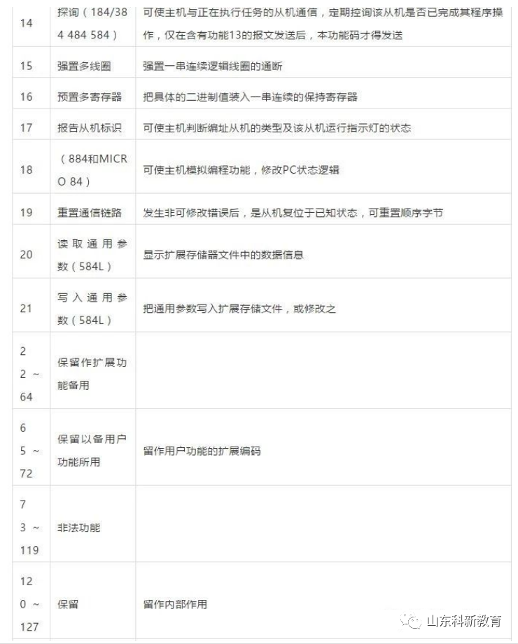
Function Code: The function code sent by the master tells the slave what action to perform. Table 1-1 lists the function codes with specific meanings and operations.
Data Area: The data area contains the actions required by the slave or the information returned by the slave. These can be values, reference addresses, etc. For example, if the function code tells the slave to read the value of a register, the data area must contain the starting address of the register to be read and the length of the read. The addresses and data information differ for each slave.
Error Check Code: The master or slave can use the check code to determine whether the received information has errors. Sometimes, due to electronic noise or other interference, information may undergo slight changes during transmission, and the error check code ensures that the master or slave does not act on erroneous information during transmission. This increases the safety and efficiency of the system. The error check uses the CRC-16 method.
Note: The format of the information frame is fundamentally the same: address code, function code, data area, and error check code.
2. Error Check
The Redundant Cyclic Code (CRC) consists of 2 bytes, or 16 bits. The CRC code is calculated by the sending device and placed at the end of the sent information. The receiving device recalculates the CRC code of the received information and compares it with the received CRC code. If the two do not match, it indicates an error.
3. Function Codes Supported by Modbus:

1. Command 01, Read Readable and Writable Digital Registers (Coil Status):
The computer sends the command: [Device Address] [Command Number 01] [Starting Register Address High 8 Bits] [Low 8 Bits] [Number of Registers to Read High 8 Bits] [Low 8 Bits] [CRC Check Low] [CRC Check High]
Example: [11][01][00][13][00][25][CRC Low][CRC High]
Meaning:
<1> Device Address: Multiple devices can be connected on an RS-485 bus; the device address indicates which device the user wishes to communicate with. In this example, it is the 17th device (decimal 17 is hexadecimal 11).
<2> Command Number 01: The command number for reading digital quantities is fixed at 01.
<3> Starting Address High 8 Bits, Low 8 Bits: Indicates the starting address of the switch quantity to be read (starting address is 0). For example, the starting address in this case is 19.
<4> Number of Registers High 8 Bits, Low 8 Bits: Indicates how many switch quantities to read starting from the starting address. In this case, there are 37 switch quantities.
<5> CRC Check: The check from the beginning up to this point.
Device Response: [Device Address] [Command Number 01] [Number of Bytes Returned] [Data 1] [Data 2] … [Data n] [CRC Check High] [CRC Check Low]
Example: [11][01][05][CD][6B][B2][0E][1B][CRC High][CRC Low]
Meaning:
<1> The device address and command number are the same as above.
<2> Number of Bytes Returned: Indicates the number of bytes of data, which is also the value of n in Data 1, 2 … n.
<3> Data 1…n: Each data is an 8-bit number, where each bit represents whether the corresponding switch is open (0) or closed (1). For example, in this case, the 20th switch (index number 19) is closed, while the 21st is open, the 22nd is closed, the 23rd is closed, the 24th is open, the 25th is open, the 26th is closed, and the 27th is closed. If the queried switch quantity is not a multiple of 8, the high part of the last byte is meaningless and should be set to 0.
<4> CRC Check is the same as above.
2. Command 05, Write Digital Quantity (Coil Status):
The computer sends the command: [Device Address] [Command Number 05] [Register Address to be Set High 8 Bits] [Low 8 Bits] [Data to be Set High 8 Bits] [Low 8 Bits] [CRC Check Low] [CRC Check High]
Example: [11][05][00][AC][FF][00][CRC High][CRC Low]
Meaning:
<1> The device address is the same as above.
<2> Command Number: The command number for writing digital quantities is fixed at 05.
<3> Register Address to be Set High 8 Bits, Low 8 Bits: Indicates the address of the switch to be set.
<4> Data to be Set High 8 Bits, Low 8 Bits: Indicates the state of the switch quantity to be set. In this case, it is to close the switch. Note that it can only be [FF][00] for closed and [00][00] for open; other values are illegal.
<5> Note that this command can only set the state of one switch quantity.
Device Response: If the command sent by the computer is successfully received, it returns the command as it is; otherwise, it does not respond.
3. Command 03, Read Writable Analog Registers (Holding Registers):
The computer sends the command: [Device Address] [Command Number 03] [Starting Register Address High 8 Bits] [Low 8 Bits] [Number of Registers to Read High 8 Bits] [Low 8 Bits] [CRC Check High] [CRC Check Low]
Example: [11][03][00][6B][00][03][CRC High][CRC Low]
Meaning:
<1> The device address is the same as above.
<2> Command Number: The command number for reading analog quantities is fixed at 03.
<3> Starting Address High 8 Bits, Low 8 Bits: Indicates the starting address of the analog quantity to be read (starting address is 0). For example, in this case, the starting address is 107.
<4> Number of Registers High 8 Bits, Low 8 Bits: Indicates how many analog quantities to read starting from the starting address. In this case, there are 3 analog quantities. Note that each analog quantity requires two bytes to return in the response.
Device Response: [Device Address] [Command Number 03] [Number of Bytes Returned] [Data 1] [Data 2] … [Data n] [CRC Check High] [CRC Check Low]
Example: [11][03][06][02][2B][00][00][00][64][CRC High][CRC Low]
Meaning:
<1> The device address and command number are the same as above.
<2> Number of Bytes Returned: Indicates the number of bytes of data, which is also the value of n in Data 1, 2 … n. In this case, it returns 3 values of analog data, as each analog quantity requires 2 bytes, totaling 6 bytes.
<3> Data 1…n: Data 1 and Data 2 are the high and low bytes of the first analog quantity, while Data 3 and Data 4 are the high and low bytes of the second analog quantity, and so on. In this case, the returned values are 555, 0, and 100.
<4> CRC Check is the same as above.
4. Command 06, Write Single Analog Quantity Register (Holding Register):
The computer sends the command: [Device Address] [Command Number 06] [Register Address to be Set High 8 Bits] [Low 8 Bits] [Data to be Set High 8 Bits] [Low 8 Bits] [CRC Check High] [CRC Check Low]
Example: [11][06][00][01][00][03][CRC High][CRC Low]
Meaning:
<1> The device address is the same as above.
<2> Command Number: The command number for writing analog quantities is fixed at 06.
<3> Register Address to be Set High 8 Bits, Low 8 Bits: Indicates the address of the analog quantity register to be set.
<4> Data to be Set High 8 Bits, Low 8 Bits: Indicates the analog quantity data to be set. For example, in this case, it sets the value of register 1 to 3.
<5> Note that this command can only set the state of one analog quantity.
Device Response: If the command sent by the computer is successfully received, it returns the command as it is; otherwise, it does not respond.
5. Command 16, Write Multiple Analog Quantity Registers (Holding Registers):
The computer sends the command: [Device Address] [Command Number 16] [Register Address to be Set High 8 Bits] [Low 8 Bits] [Number of Data High 8 Bits] [Data Quantity Low 8 Bits] [Data to be Set High 8 Bits] [Low 8 Bits] […] [CRC Check High] [CRC Check Low]
Example: [11][16][00][01][00][01][00][05][CRC High][CRC Low]
Meaning:
<1> The device address is the same as above.
<2> Command Number: The command number for writing analog quantities is fixed at 16.
<3> Register Address to be Set High 8 Bits, Low 8 Bits: Indicates the address of the analog quantity register to be set.
<4> Data Quantity High 8 Bits, Low 8 Bits: Indicates the number of data to be set; here it is 1.
<5> Data to be Set High 8 Bits, Low 8 Bits: Indicates the analog quantity data to be set. For example, in this case, it sets the value of register 1 to 5.
Device Response: If the command sent by the computer is successfully received, it returns the command as it is; otherwise, it does not respond.
Source: This article is adapted from the internet; copyright belongs to the original author. If there are any copyright issues, please contact us for deletion. Thank you!

Scan to Follow
WeChat ID|13615417996
Follow the left QR code to get it for free
[Siemens Data Collection]