Click↑↑ to follow JiCheng Training and pin it to your top for long-term free subscription
Over 190,000 industrial control professionals follow this WeChat platform: technical sharing, learning exchange, industrial control videos
PLC Control Cabinet refers to a complete control system that can control motors and switches within an electrical cabinet.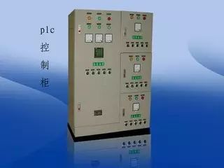 PLC control cabinets have functions such as overload, short circuit, and phase loss protection. Their compact structure, stable operation, and comprehensive functionality allow for combinations based on actual control scale, enabling both single cabinet automatic control and multiple cabinets to form a distributed control system (DSC) through industrial Ethernet or fieldbus networks. They can adapt to various scales of industrial automation control scenarios and are widely used in industries such as power, metallurgy, chemical, paper-making, and environmental wastewater treatment.PLC control cabinets can achieve automation of equipment and processes, providing excellent network functionality, stable performance, expandability, and strong anti-interference capabilities, making them the core and soul of modern industry. Users can design PLC control cabinets, frequency conversion cabinets, etc., according to their needs, and can pair them with human-machine interface touch screens for easy operation.Typical applications include constant pressure water supply, air compressors, fans and pumps, central air conditioning, port machinery, machine tools, boilers, paper-making machinery, food machinery, and more.Now, let’s go over some basic knowledge~
 Components of a PLC Control Cabinet1. Air SwitchA main air switch, which controls the power supply for the entire cabinet, is essential for every cabinet.
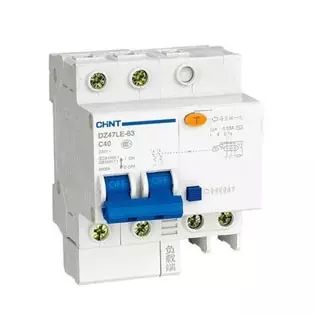 2. PLCThis should be selected based on project needs. For smaller projects, an integrated PLC may suffice; for larger projects, modular or card-based PLCs may be required, possibly with redundancy (i.e., two sets operating alternately).
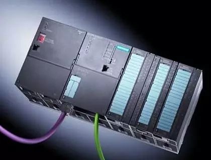 3. 24VDC Power SupplyA 24VDC switching power supply. Most PLCs come with a built-in 24VDC power supply, but whether this switching power supply is needed depends on the actual situation.
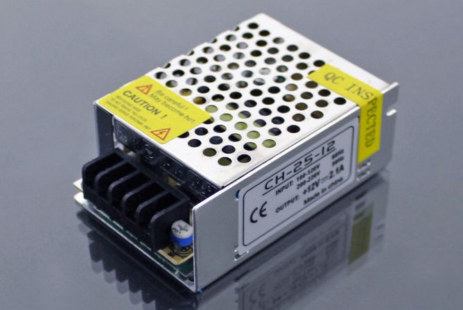 4. RelayGenerally, the PLC can directly send commands to the control circuit, but it may also go through a relay first. If the output of your PLC is 24VDC, but the control circuit requires 220VAC, you must add a relay at the PLC output. When the command is issued, the relay activates, connecting the control circuit to the relay’s normally open or normally closed points. The use of relays depends on the situation.
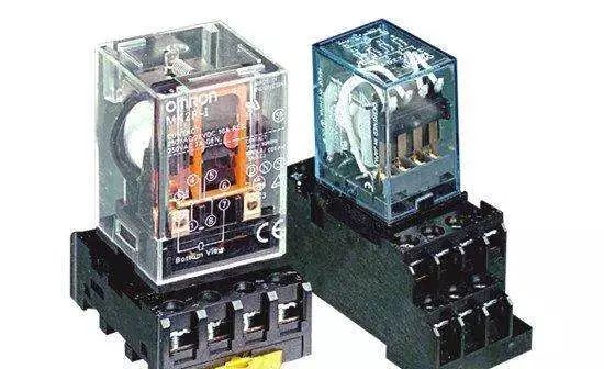 5. Terminal BlocksThese are essential for every cabinet and can be configured based on the number of signals. If it is just a simple PLC control cabinet, these components are generally sufficient. If your control cabinet needs to accommodate other devices, you may need to add more components. For example, if you need to power certain field instruments or small control boxes, you may need to increase the number of air switches. Or if you need to connect the PLC to a host computer, you may need to add a switch, depending on the situation.
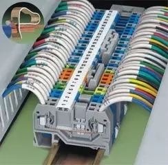 Operating Conditions for PLC Control CabinetsPower Supply:DC 24V, single-phase AC 220V, (-10%, +15%), 50HzProtection Level:IP41 or IP20Environmental Conditions:Ambient temperature between 0℃-55℃, preventing direct sunlight; relative humidity should be less than 85% (no condensation). Keep away from strong vibration sources, avoiding frequent or continuous vibrations at frequencies of 10-55HZ. Avoid corrosive and flammable gases.Basic Structure1. Power SupplyThe power supply for the programmable logic controller plays a crucial role in the entire system. Without a good, reliable power supply system, normal operation is impossible. Therefore, PLC manufacturers pay great attention to the design and manufacturing of power supplies. Generally, if the AC voltage fluctuation is within +10% (+15%), the PLC can be directly connected to the AC power grid without additional measures.2. Central Processing Unit (CPU)The CPU is the control center of the programmable logic controller. It receives and stores user programs and data input from the programmer according to the functions assigned by the PLC system program; checks the status of the power supply, memory, I/O, and watchdog timers, and can diagnose syntax errors in the user program.When the PLC is put into operation, it first scans the status and data of all input devices in the field and stores them in the I/O image area. Then, it reads the user program from the user program memory line by line, interprets the commands, and executes the logical or arithmetic operations as specified, sending the results to the I/O image area or data registers. After all user programs are executed, the output states or data in the I/O image area are sent to the corresponding output devices, and this cycle continues until stopped.To further enhance the reliability of PLCs, recent years have seen the adoption of dual CPU redundant systems or triple CPU voting systems for large PLCs. This way, even if one CPU fails, the entire system can continue to operate normally.3. MemoryThe memory that stores the system software is called system program memory.The memory that stores application software is called user program memory.4. Input/Output Interface Circuits1. The field input interface circuit consists of optocoupler circuits and the microcomputer’s input interface circuit, serving as the input channel for the PLC to interface with field control.2. The field output interface circuit integrates output data registers, gating circuits, and interrupt request circuits, allowing the PLC to output corresponding control signals to field actuators through the field output interface circuit.5. Functional ModulesSuch as counting, positioning, and other functional modules.6. Communication ModulesWorking Principle: When the PLC is put into operation,its working process is generally divided into three stages, namely input sampling, user program execution, and output refreshing. Completing these three stages is called a scan cycle. During the entire operation, the PLC’s CPU repeatedly executes these three stages at a certain scan speed.1. Input Sampling StageIn the input sampling stage, the PLC reads all input statuses and data sequentially in a scanning manner and stores them in the corresponding units of the I/O image area. After input sampling is complete, it transitions to the user program execution and output refreshing stages. In these two stages, even if the input status and data change, the states and data in the corresponding units of the I/O image area do not change. Therefore, if the input is a pulse signal, the width of that pulse signal must be greater than one scan cycle to ensure that the input can be read under any circumstances.2. User Program Execution StageIn the user program execution stage, the PLC always scans the user program (ladder diagram) in a top-down order. When scanning each ladder diagram, it first scans the control circuits composed of contacts on the left side of the ladder diagram, performing logical operations on the control circuits in a left-to-right, top-to-bottom order. Then, based on the results of the logical operations, it refreshes the state of the corresponding bits in the system RAM storage area for that logic coil; or refreshes the state of the corresponding bits in the I/O image area for that output coil; or determines whether to execute the special function instructions specified by the ladder diagram.That is, during the user program execution process, only the input points’ states and data in the I/O image area do not change, while the states and data of other output points and soft devices in the I/O image area or system RAM storage area may change. Moreover, the results of the program execution for the ladder diagrams above will affect those below that use these coils or data; conversely, the logic coils’ states or data refreshed by the ladder diagrams below can only affect the programs above in the next scan cycle.If immediate I/O instructions are used during the program execution, they can directly access I/O points. That is, when using I/O instructions, the values in the input process image registers will not be updated, and the program will directly take values from the I/O module, while the output process image registers will be immediately updated, which differs from immediate input.3. Output Refresh StageAfter the user program scanning is complete, the PLC enters the output refresh stage. During this period, the CPU refreshes all output latch circuits according to the corresponding states and data in the I/O image area, and then drives the corresponding external devices through the output circuits. This is the true output of the PLC.Characteristics of Programmable Logic Controllers1. The system structure is flexible and easy to expand, with digital control as its specialty; it can also perform continuous process PID loop control; and can form complex control systems with upper-level devices, such as DDC and DCS, achieving comprehensive automation of production processes.2. User-friendly, simple programming, using clear ladder diagrams, logic diagrams, or statement lists as programming languages, without requiring computer knowledge, thus shortening the system development cycle and facilitating on-site debugging. Additionally, programs can be modified online, changing control schemes without disassembling hardware.3. It can adapt to various harsh operating environments, with strong anti-interference capabilities and high reliability, far exceeding other types of models.Source: Internet, copyright belongs to the original author, infringement will be deletedFollow JiCheng Xiao Qi>>>to receive valuable electrical materials
 If you find this article helpful, please click Read More~
Click↓Read the original text to learn electrical knowledge such as electrical engineering and PLC for free!