In PLC, there are mainly three types of quantities:Switching Quantity, Analog Quantity, Pulse Quantity. Understanding the relationship between these three will allow you to master PLC proficiently.
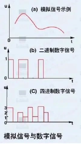
1. Switching Quantity, also known as logical quantity, refers to only two values, 0 or 1, ON or OFF (Switching quantity has only two states 0/1, including input and output quantities, reflecting a state). It is the most commonly used control, and controlling it is the advantage of PLC and its most basic application.
The purpose of switching quantity control is to produce corresponding switching quantity output based on the current input combination and historical input sequence, so that the system can operate in a certain sequence. Therefore, it is sometimes also referred to as sequential control.
Sequential control can be divided into manual, semi-automatic, or automatic. The control principles used can be decentralized, centralized, or mixed control.
2. Analog Quantity refers to some continuously changing physical quantities (Digital quantity is discontinuous. It reflects the measured value of electrical quantities), such as voltage, current, pressure, speed, flow, etc.
PLC was developed after the introduction of microprocessing technology from relay control, making it convenient and reliable for switching quantity control. Sinceanalog quantity can be converted into digital quantity, and digital quantity is merely multiple bits of switching quantity, the converted analog quantity can also be reliably processed and controlled by PLC.
Since continuous production processes often involve analog quantities, analog quantity control is sometimes also referred to as process control.
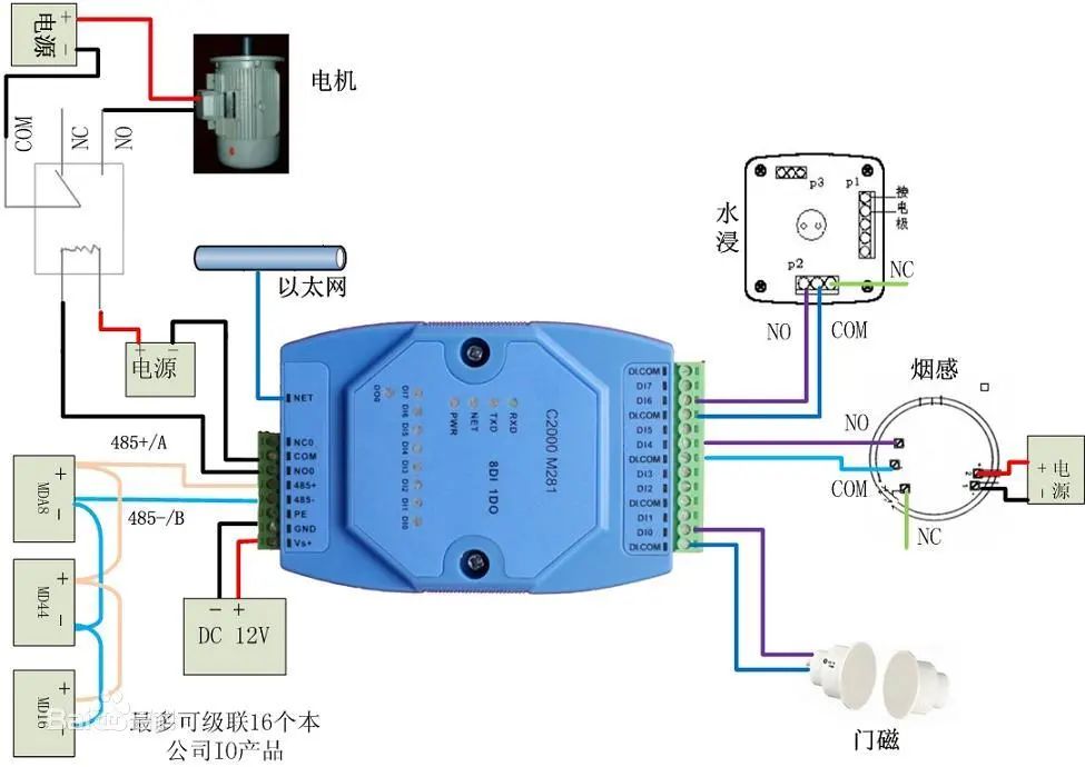
Analog quantities are mostly non-electrical quantities, while PLC can only process digital quantities and electrical quantities. Therefore, to achieve conversion between them, sensors are needed to convert analog quantities into digital electrical quantities.
If this electrical quantity is not standard, it must go through a transmitter to convert the non-standard electrical quantity into a standard electrical signal, such as 4-20mA, 1-5V, 0-10V, etc.
At the same time, there must be an analog input unit (A/D) to convert these standard electrical signals into digital signals. An analog output unit (D/A) converts the processed digital quantity back into analog quantity—standard electrical signals.
Thus, the conversion between standard electrical signals and digital quantities requires various calculations. This necessitates understanding the resolution of the analog quantity unit and the standards of electrical signals.
For example:
The resolution of the PLC analog unit is 1/32767, corresponding to a standard electrical quantity of 0-10V, with the temperature value to be detected being 0-100℃. Then 0-32767 corresponds to the temperature value of 0-100℃. The digital quantity corresponding to 1℃ is calculated to be 327.67. If you want to achieve precision to 0.1℃, you can use 327.67/10.
Analog quantity control includes: feedback control, feedforward control, proportional control, fuzzy control, etc. These are all the calculation processes of internal digital quantities in the PLC.
3. Pulse Quantity refers to a digital quantity that constantly alternates between 0 (low level) and 1 (high level) (the instantaneous voltage or current jumps from one value to another), with the number of pulse alternations per second referred to as frequency.
The main purpose of PLC pulse quantity control is for position control, motion control, trajectory control, etc. For example: the application of pulse count in angle control. The subdivision of a stepper motor driver is 10000 per revolution, requiring the stepper motor to rotate 90 degrees.
Then the pulse count needed for action = 10000/(360/90) = 2500
1. -10—10V. When the voltage is -10V—10V, it is converted to F448—0BB8Hex(-3000—3000) at a resolution of 6000; at a resolution of 12000, it is converted to E890—1770Hex(-6000—6000).
2. 0—10V. When the voltage is 0—10V, at a resolution of 12000, it is converted to 0—1770Hex(0—6000); at a resolution of 12000, it is converted to 0—2EE0Hex(0—12000).
3. 0—20mA. When the current is 0—20mA, at a resolution of 6000, it is converted to 0—1770Hex(0—6000); at a resolution of 12000, it is converted to 0—2EE0Hex(0—12000).
4. 4—20mA. When the current is 4—20mA, at a resolution of 6000, it is converted to 0—1770Hex(0—6000); at a resolution of 12000, it is converted to 0—2EE0Hex(0—12000).
The above is just a simple introduction; different PLCs have different resolutions, and the measurement range of the physical quantities you measure may vary. The calculation results may have some differences.
Note: Requirements for Wiring of Analog Inputs
1. Use shielded twisted pair cable, but do not connect the shield layer.
2. When an input is not used, short-circuit the V IN and COM terminals.
3. Isolate the analog signal line from the power line (AC power line, high voltage line, etc.).
4. When there is interference on the power line, install a filter between the input part and the power unit.
5. After confirming the wiring is correct, first power on the CPU unit, then power on the load.
6. When cutting power, first cut off the power to the load, then cut off the power to the CPU.
Pulse quantity control is often used for angle control, distance control, position control of stepper motors and servo motors, etc. The following uses a stepper motor as an example to illustrate each control method.
1. Angle control of the stepper motor. First, clarify the subdivision number of the stepper motor, and then determine the total pulse count required for the stepper motor to make one full rotation.

Calculate “Angle Percentage = Set Angle / 360° (i.e., one full rotation)”
“Angle Action Pulse Count = Total Pulse Count per Revolution * Angle Percentage”
The formula is:
Angle Action Pulse Count = Total Pulse Count per Revolution * (Set Angle / 360°)
2. Distance control of the stepper motor. First clarify the total pulse count required for the stepper motor to make one full rotation. Then determine the diameter of the stepper motor wheel, calculate the circumference of the wheel. Calculate the distance traveled per pulse. Finally, calculate the pulse count required to cover the set distance.

The formula is:
Set Distance Pulse Count = Set Distance / [(Wheel Diameter * 3.14) / Total Pulse Count per Revolution]
3. Position control of the stepper motor is a combination of angle control and distance control.
The above is just a simple analysis of the control methods for stepper motors, which may differ from actual applications, for reference only.
The operation of servo motors is similar to that of stepper motors, but considerations must be made for the internal gear ratio of the servo motor and the reduction ratio of the servo motor.
After reading, I deeply feel the difficulty of learning, cherish it while learning! Finally, I would like to ask everyone one last question: How to learn PLC?
How can you find the key points and improvement directions of skills in the shortest possible time while also establishing your own learning planning system!!!
Learning PLC is a gradual process, step by step. If you are willing to put in the effort, even with a middle school education, you can learn to be proficient, while a college education can lead to mastery, so please do not give up easily if you encounter difficulties.
As the ancients said, “Learning without thinking leads to confusion, and thinking without learning leads to danger,” which means that before learning knowledge, one should think about how to learn? What process to follow?
At the same time, combining with practice can maximize the usefulness of the knowledge learned, rather than just theoretical discussions.
Therefore, today I will share with everyone the accumulated knowledge, which includes Siemens, Mitsubishi, Omron, etc., PLC introductory knowledge, learning plans, programming cases, and simulation software.
1
PLC Introductory Learning Plan
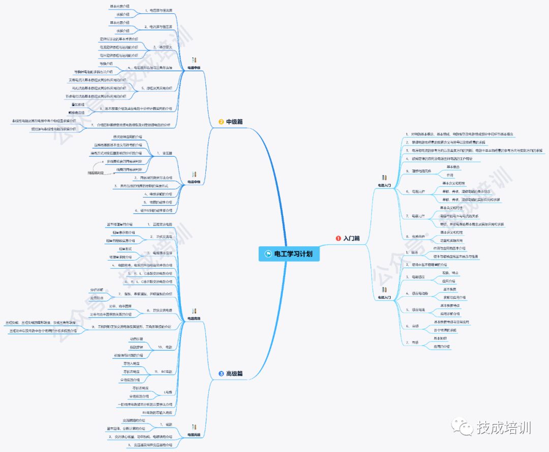
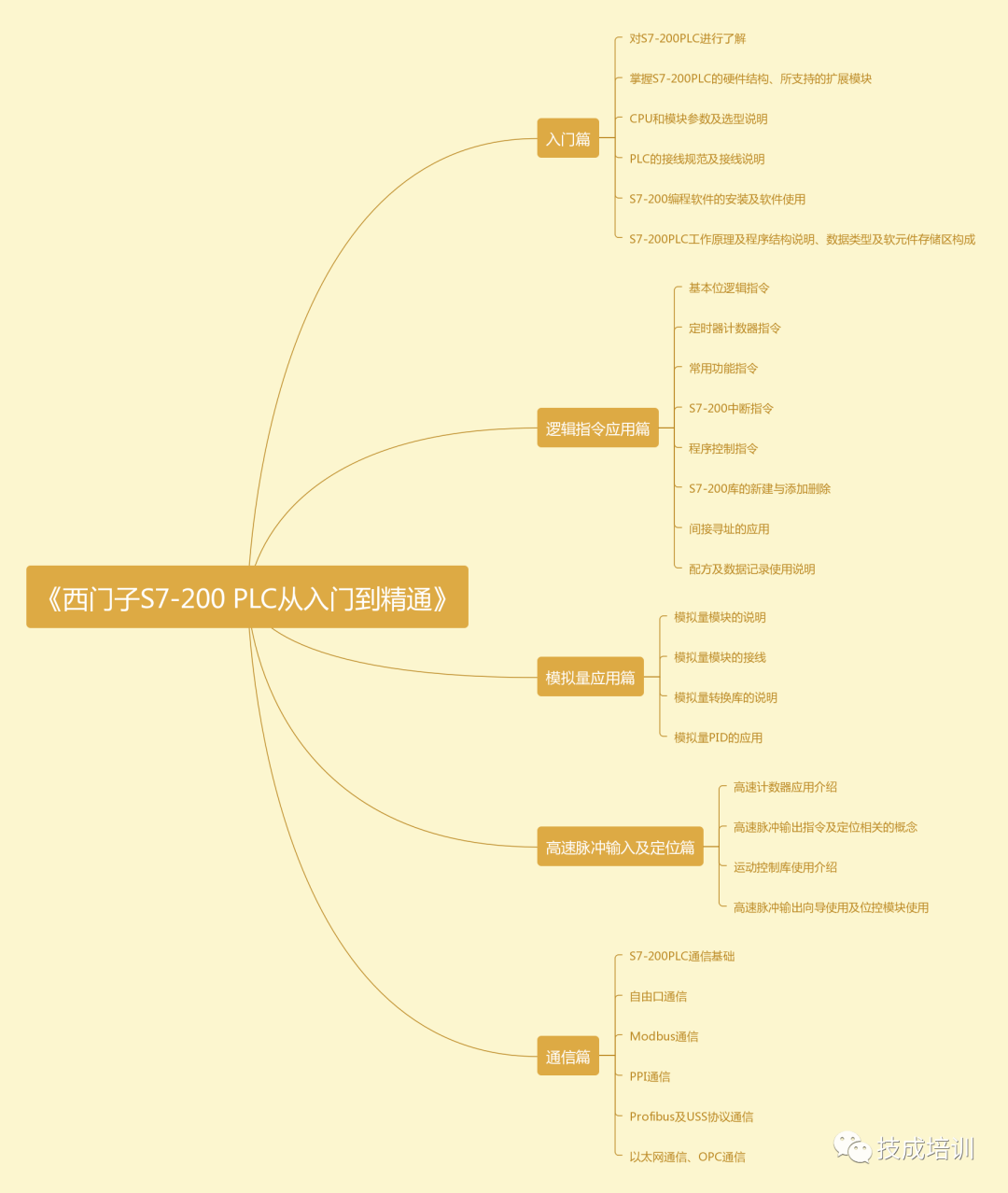
Siemens S7-200 from Beginner to Mastery
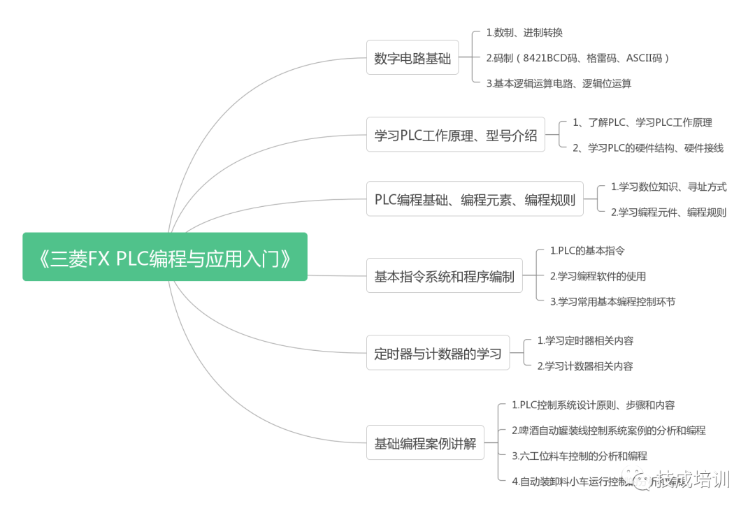
Mitsubishi Learning Plan
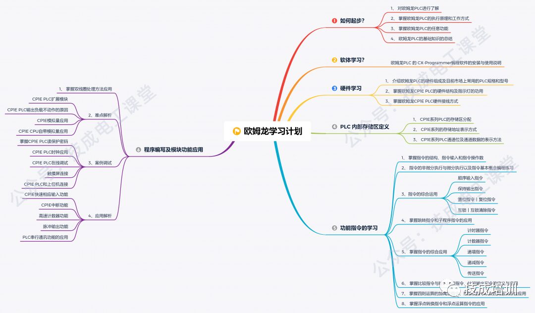
Omron Learning Plan

Scan to participate and receive
280G PLC Materials + 3 Learning Plans
2
PLC Learning Materials
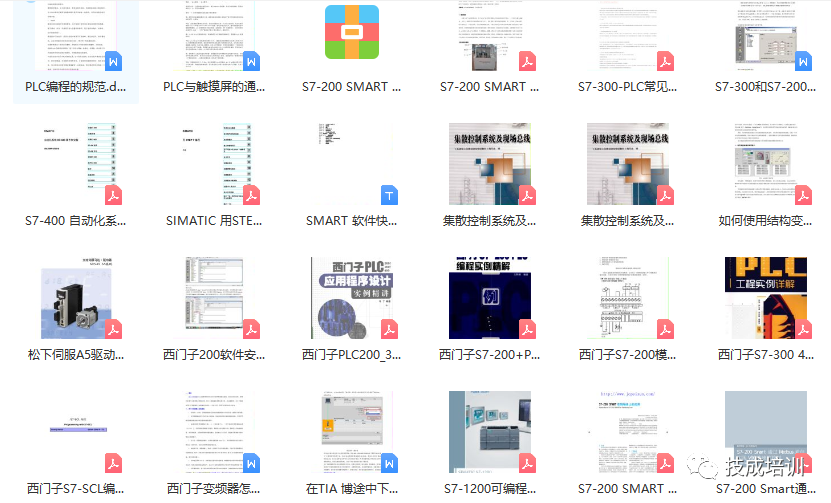
Siemens Materials (Learning Manual + Case Studies + E-Books)
……
▲Learning Materials
▲777+ Cases
Mitsubishi Materials (Learning Manual + Case Studies + E-Books)
……
▲Learning Materials

▲Programming Cases
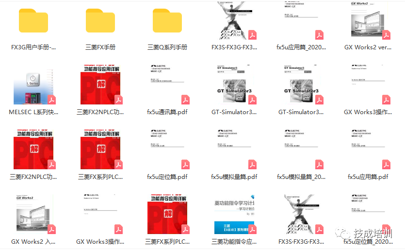
▲Manuals + Instructions

Scan to receive
280G PLC Materials + 3 Learning Plans
3
PLC Programming Simulation Software
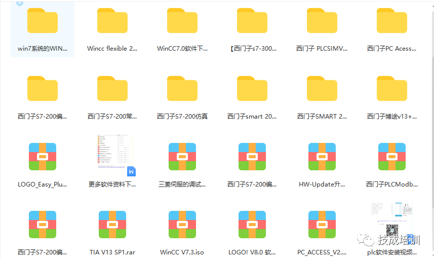
Siemens Software (Programming Simulation Software + Configuration, etc.)
Mitsubishi Software (Including Learning Software + Programming Simulation Software)
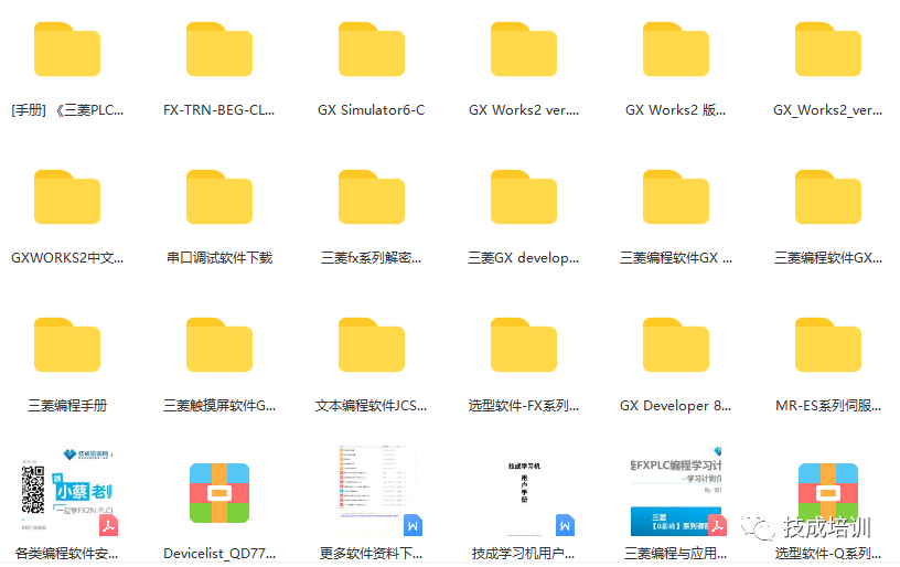
Attached Software Installation Tutorial
Due to space limitations, to obtain more materials, please scan the QR code below, filled with 280G waiting for you to collect, you are just one step away from becoming an excellent electrical engineer!

Scan to receive
280G PLC Materials + 3 Learning Plans
2021 Electrician Beginner Exam Question Bank Complete (Including Answers)
3 Essential Tools for Electricians, Open with WeChat!
【Collection】 The “Path” of a Ten-Year Veteran Electrician, Secrets to Earning Over Ten Thousand Monthly!
Which of the Five Major Electrical Drafting Software (CAD, Eplan, CADe_simu…) Do You Pick?
Latest Electrical Version CAD Drawing Software, with Detailed Installation Tutorial!
Latest Electrical Drawing Software EPLAN, with Detailed Installation Tutorial!
Common Issues for Beginners Using S7-200 SMART Programming Software (Including Download Links)
Comprehensive Electrical Calculation EXCEL Sheets, Automatically Generated! No Need for Help with Electrical Calculations!
Bluetooth Headphones, Books for Electricians/PLC Beginners? Come and Get Your Electrical Gifts!
Basic Skills of PLC Programming: Ladder Diagram and Control Circuits (Including 1164 Practical Cases for Mitsubishi PLC)
Still Can’t Understand Electrical Diagrams? Basics of Electrical Drawing, Simulation Software, Quick Hands-On Theory and Practice!
12 Free Electrician Video Courses, 10GB Software/E-Book Materials, 30 Days of Free Live Electrician Courses!