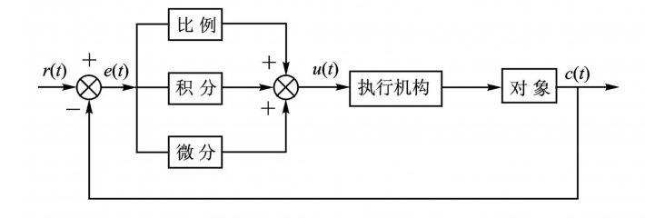
When learning and using PID, there are many motor options available. However, the PID parameters used for different motors can vary significantly. Therefore, we need to understand motors and drivers.
1 Types of Motors
1.1 Introduction to Motors
A motor is a device that can convert electrical energy into mechanical energy and vice versa. Generators convert mechanical energy into electrical energy, while motors convert electrical energy into mechanical energy.
Generators are primarily used to produce electrical energy and have a singular purpose, whereas motors are used to generate mechanical energy and have a wide range of applications.
Motors can be categorized into two types: electric motors and generators. The former converts electrical energy into mechanical energy, while the latter converts mechanical energy into electrical energy.
1.2 Classification of Motors
There are various types of motors, and thus many classification methods. They can be classified based on the type of power supply, structure and working principle, starting and operating methods, applications, operating speeds, and more. In practical applications, engineers classify motors based on their characteristics.
For example, a DC motor is chosen for high-speed requirements, while a stepper motor is selected for high precision. Next, we will select a few representative and commonly used motors from the many types available.
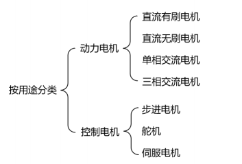
Motors can be classified based on their power supply, application, rotor structure, operating speed, etc. Here, we will classify common motors based on their applications, as shown in the diagram below.
1.2.1 DC Motors
DC motors can be further divided into standard DC motors, DC geared motors, brushed and brushless types, which include:
-
Brushed DC Motor
A brushed DC motor (BDC) is a type of motor that contains a brush mechanism to convert DC electrical energy into mechanical energy. Within the allowable range, adjusting the voltage can change its speed, giving this type of motor excellent speed control performance. This type of motor can be used to create balance cars, balance bicycles, etc.
-
Brushed DC Geared Motor
Brushless motors are those without brushes and commutators (or collector rings), also known as brushless commutation motors. They consist of a motor body and a driver, making them a typical mechatronic product.
Brushless motors appeared as early as the 19th century, specifically in the form of AC squirrel-cage asynchronous motors. However, they had many insurmountable flaws, leading to continuous exploration for better motor technologies.
It wasn’t until the mid-20th century, with the advent of transistors, that transistor commutation circuits replaced traditional brush and commutator structures, overcoming the defects of the first generation of brushless motors. Our drones can utilize this type of motor.
-
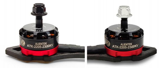
Brushless DC Motor
-
Brushless DC Geared Motor
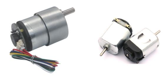
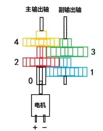
These four types of motors. As the name suggests, the only difference between a standard DC motor and a DC geared motor is the “gearing”; they differ in structure by a gear reduction system.
In a standard DC motor, the speed under no load is determined by the voltage; the speed of a DC geared motor is determined by both the gear ratio and the voltage; the gear system provides lower speed and higher torque; different gear ratios will provide different speeds and torques.
This greatly increases the usability of geared motors.
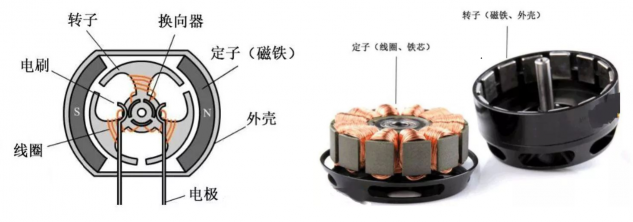
Next, we discuss the differences between brushed and brushless motors: the terms brushed and brushless refer to the presence or absence of carbon brushes; brushed motors require the coils and commutators to rotate while the magnets and brushes remain stationary. The alternation of the coil current direction is completed by the commutator and brushes as the motor rotates.
Brushless DC motors use semiconductor switching devices to achieve electronic commutation, replacing traditional contact-type commutators and brushes.
1.2.2 Stepper Motors
Stepper motors are open-loop control motors that convert electrical pulse signals into angular or linear displacements. They are the main execution components in modern digital program control systems and are widely used. Under non-overload conditions, the speed and stopping position of a stepper motor depend solely on the frequency and number of pulse signals, unaffected by load changes.
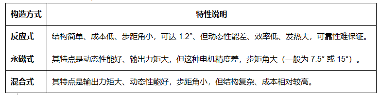
Stepper motors can convert pulse signals into angular or linear displacements. At low frequencies under no load, one pulse equals one step, allowing for precise control of rotation angles. Stepper motors can be classified into three types based on their construction: reactive, permanent magnet, and hybrid.
Based on the stator winding, they can be divided into two-phase, three-phase, and five-phase series, but the most popular is the two-phase hybrid stepper motor, which occupies about 97% of the market share, essentially dominating the entire market. Therefore, the following discussion will mainly focus on two-phase hybrid stepper motors.
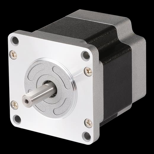
You may have heard of the 42 stepper motor; what does “42” refer to? The following image will explain what “42” means.
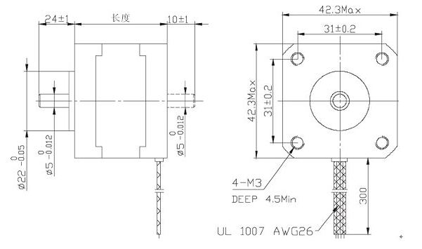
The 42 stepper motor refers to the step size, and hybrid stepper motors are generally square, with an outer frame size of 42mm x 42mm. Besides 42, there are also 57 stepper motors and 86 stepper motors, named after their outer frame sizes.
1.2.3 Servo Motors
The term “servo” comes from the Greek word for “slave,” so a servo motor can be understood as a motor that absolutely obeys the control signal. Therefore, a servo motor refers to a motor that is controlled within a servo system.
If we refer to a motor alone, it can only be considered a controlled mechanical component, but when combined with a closed-loop control system, it can be called a motor within a servo system.
Servo motors are electric motors that control the operation of mechanical components within a servo system. When paired with a driver, they form a complete servo system capable of precisely controlling speed, position, and other parameters. Servo motors are characterized by high linearity, large starting torque, a wide operating range, and no self-rotation phenomenon.
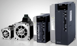
Servo motors are divided into two main categories: DC and AC servo motors. Their main characteristics include no self-rotation phenomenon when the signal voltage is zero, and the speed decreases uniformly with increasing torque.
Characteristics of DC servo motors: The mechanical characteristics change when the input armature voltage remains constant; the motor speed varies with the electromagnetic torque; the regulation characteristics of DC motors change the steady-state speed with varying control voltage under a certain electromagnetic torque (or load torque); dynamic characteristics involve a transition process from the original stable state to a new stable state.
Characteristics of AC servo motors: They have no brushes and commutators, making them reliable in operation with low maintenance requirements; the stator winding dissipates heat conveniently; they have low inertia, making it easy to improve system responsiveness; they are suitable for high-speed, high-torque operating conditions.
1.2.4 Servos
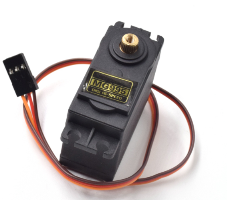
Servos are a “special” type of DC motor, as they not only consist of the motor part but also include a built-in controller, making the servo itself a closed-loop control system (servo system).
When we send a command signal to the servo, it can convert the command signal into the angle of the output shaft and maintain it, even if the load changes, it can automatically adjust.
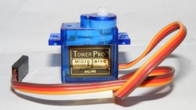
Servos are common servo motors composed of a small DC motor, control circuit board, potentiometer, and gear system. They have a wide range of applications; servos can be classified based on signal type, gear type, and application; they are divided into 90°, 180°, 270°, and 360° servos, with 180° servos being the most common.
Classified by signal type into analog servos and digital servos
Analog Servos: No MCU microcontroller, the circuit is analog, and there will be performance differences among the same type of servos.
Digital Servos: Have an MCU controller, generally optimized with internal algorithms, offering better performance than analog servos.
Classified by gear type into metal gear servos and plastic gear servos:
Metal Gear Servos: Suitable for high torque and high-speed applications.
Plastic Gear Servos: Low cost, suitable for medium to low torque applications.
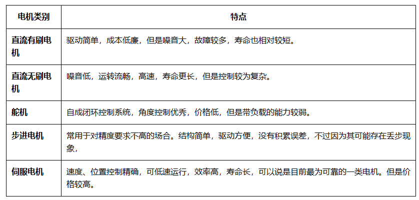
1.3 Characteristics of Various Motors
1.4 Common Terminology in Motors
① Speed: The speed of the motor’s output shaft, usually measured in r/min (revolutions per minute), often represented as RPM.
② Output Torque: Indicates the magnitude of force that the motor’s output shaft can exert, typically measured in N·m or kg·cm.
③ Operating Voltage: The voltage at which the motor operates normally.
④ Rated Current: The current at which the motor operates normally.
⑤ Stall Current: The current when the motor is overloaded, and the driving force is insufficient, causing it to stall.
2 What Types of Drivers Are There?
2.1 Brushed Motor Drivers
The driving method for brushed DC motors essentially uses an H-bridge circuit for driving, with the core circuit being the H-bridge along with some necessary peripheral circuits, forming the driver for brushed DC motors.
The H-bridge can be used as an integrated circuit or constructed from discrete components. Integrated circuit H-bridges are generally used for medium to small power applications or in situations where circuit area is a concern.
Discrete component H-bridges are typically used for high power or ultra-high power applications, mainly composed of MOSFETs or IGBT transistors.
However, the MCU pins cannot directly drive MOSFETs and other components, requiring a dedicated MOSFET driver chip.
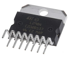
The following image shows a classic brushed DC motor driver chip, L298N, which integrates two H-bridges internally.
2.2 Brushless Motor Drivers
Brushless motors are also driven using H-bridge circuits, but each phase of the motor is driven by a half-bridge circuit. A three-phase brushless motor requires a total of three half-bridges, unlike the full-bridge circuit used for driving brushed DC motors.
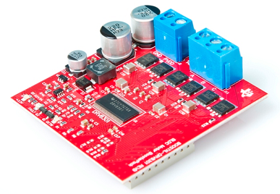
Similar to brushed DC motor drivers, brushless motor drivers are also available in integrated circuit and discrete component forms, but because brushless motors require commutation operations, even discrete component forms only separate the half-bridge circuits. The following image shows a brushless motor driver.
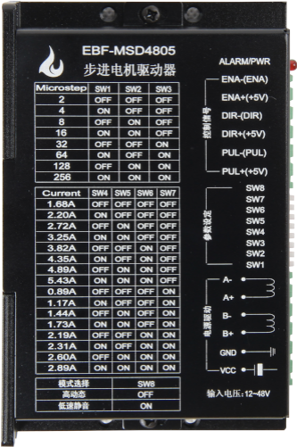
2.3 Stepper Motor Drivers
Stepper motors cannot be directly connected to DC or AC power sources; they must be connected to dedicated drivers to function properly.
The controller sends step pulse and direction signals to the stepper motor driver, which converts the step pulse signals from the controller into power signals required to excite the stepper motor to rotate.
Stepper motor drivers typically come with subdivision functions, allowing for subdivision of step angles and currents, enabling more precise control and lower noise vibrations.
2.4 Servo Motor Drivers
Servo motor drivers are controllers used to drive and control servo motors, forming part of the servo system.
Servo motor drivers receive and amplify command signals from the control system and transmit current to the servo motor to produce motion proportional to the command signals. These command signals typically control parameters such as the position, speed, and torque of the servo motor, achieving high-precision positioning in transmission systems.
Sensors attached to the servo motor provide feedback on the actual state of the motor to the servo driver, which compares the actual motor state with the command state from the control system. The driver then adjusts the voltage, frequency, or pulse width sent to the motor to correct any deviations from the command state.
3 Applications of PID
Many projects in our daily lives utilize motors and PID.
-
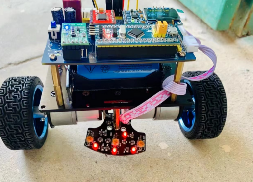
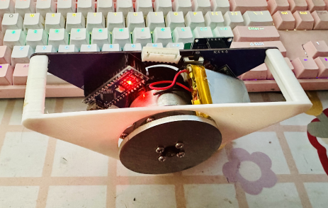
Balance Car
-
Balance Prism
“Robot Grasping Based on Deep Learning”
This course will guide you through the concepts and classifications of robot planar grasping algorithms based on deep learning, starting from scratch to build a grasp detection dataset and train the classic grasp detection network GGCNN, achieving the use of a simulated robotic arm to grasp 3D object models in a simulation environment, as well as using a Kinova robotic arm to grasp objects in real experimental scenarios.

(Scan the QR code for course details)
 Click to read the original text to view the course