Project Name: V3S-PI, A Portable Terminal Based on Allwinner V3S
Author: FanHuaCloud
To master a skill, one must rely on practice.
The author wanted to learn Linux, so he learned while doing, successfully open-sourcing a—quite good four-layer board design terminal device.
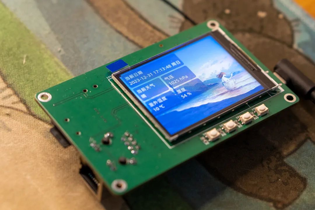
The project cost can be compressed to under 100 yuan, making it easy to replicate and learn from!
A portable terminal based on the V3S chip was created, named V3S-PI.
It has 9 functions—get weather, connect headphones to play music, 10M/100M Ethernet interface, connect to WiFi, access SD card, adjust screen brightness, button control, connect other devices, and 1-to-4 USB HUB.
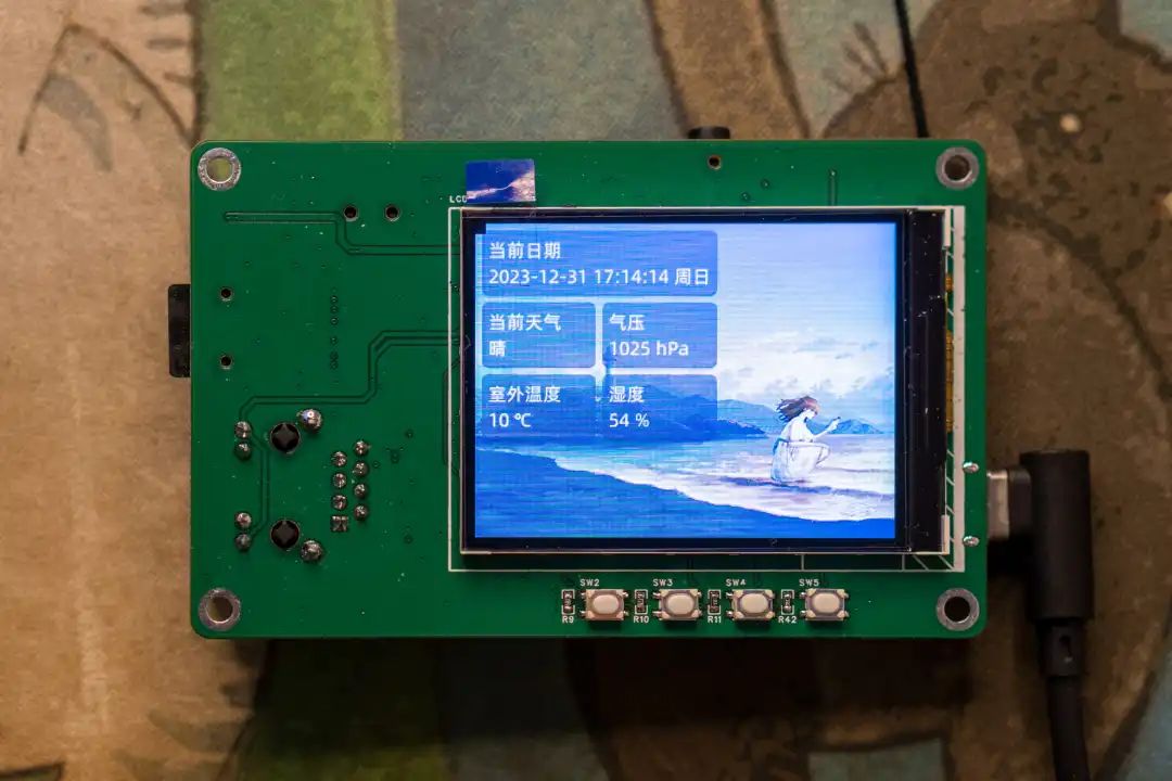
Next, I will share its—chip characteristics, project features, software open source, hardware open source, software solutions, and open source URLs.
The processor integrates a single ARM Cortex-A7 CPU, running at 1.2GHz, supporting numerous peripheral devices.
512Mbt DDR2 is highly integrated in V3.
SPINAND/NOR flash memory, SD/MMC has an external memory interface.
Supports video engine with formats like: 720P @ 60FPS, H.264 decoder, 1080p.
Can meet the demands of automotive digital video recording (DVR) and IP camera (IPC) monitoring systems.
Allwinner V3S main control, using single-core Cortex-A7, with hardware floating point.
The chip has 64Mbyte DDR2 built-in, no need for an external DDR2 chip.
Supports RTL8723BS 2.4G WiFi (SDIO interface).
Expands dual USB ports through CH334R.
The headphone interface uses the built-in sound card of V3S.
Supports 10M/100M Ethernet interface.
Supports SDMMC interface for system boot.
Supports CH340N serial to USB for connecting serial terminals.
Supports LRADC, four ADC keys (not yet tuned).
2.4-inch LCD color screen, using SPI interface.
2×8 expansion interface for extending I2C/UART.
Based on the current online materials, the author ported the mainline kernel Uboot and root by himself.Currently only supports SD card and SPI Nor booting, please do not refer to the current code for SPI Nand booting.
① UBoot
Quick Start
git clone https://gitee.com/fhcloud/uboot-v3scd uboot-v3smake v3s_pi_defconfigmakeThe output file is in the root directory of the source code: u-boot-sunxi-with-spl.bin
② Linux
Quick Start
git clone https://gitee.com/fhcloud/linux-v3scd linux-v3smake v3s_pi_defconfigmakeThe output kernel file is in arch/arm/boot/zImage
The output device tree should use arch/arm/boot/dts/sun8i-v3s-pi.dtb
③ Buildroot
Quick Start
git clone https://gitee.com/fhcloud/buildroot-v3s.gitcd buildroot-v3smake v3s_pi_defconfigmakeThe output file is in output/images/rootfs.tar
Test image account: root, password: 123456

① Main Control Part
The main control of this project uses Allwinner V3S. It should be noted that R3/R5 resistors must use 1%, and there are two groups of voltages for EPHY.
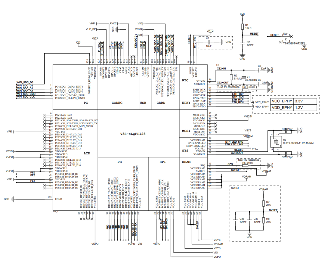
Figure 1 Main Control Schematic
② ADC Keys
The board has four ADC keys, with a voltage span of 0.2V, implemented through voltage divider resistors.

Figure 2 ADC Keys
③ 2×16 PIN Expansion Interface
This uses pin headers to bring out 8 expansion interfaces, including one serial port/one I2C bus, which can be used to connect other devices.
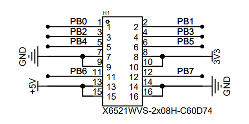
Figure 3 Expansion Interface
④ Auxiliary Power Supply
The board has four power supply chips, producing 3.0V, 3.3V, 1.8V, 1.2V, among which
-
3.0V is used for PLL and AVCC analog power supply. -
3.3V is responsible for chip IO and other peripheral power supply. -
1.8V is used for memory power supply. -
1.2V is used for V3S core main control power supply.
Three DC-DC converters have a maximum output current of 2A.
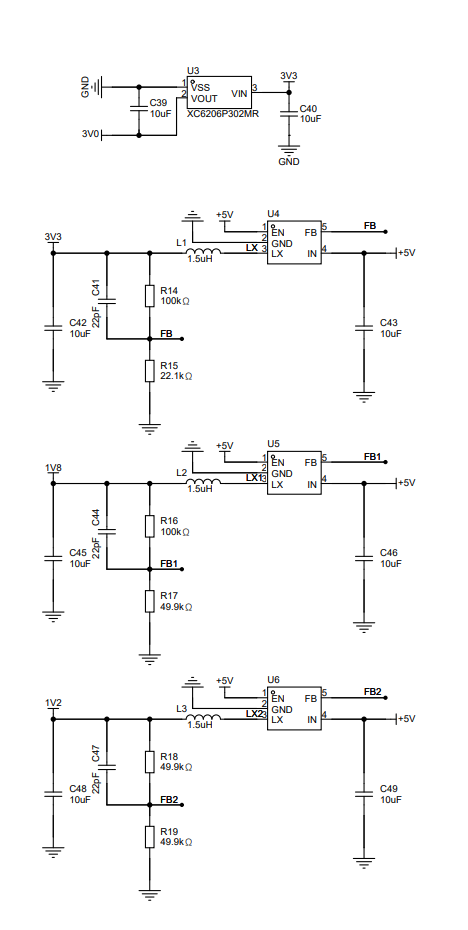
Figure 4 Auxiliary Power Supply
⑤ WIFI Module
The board has a 2.4G WIFI module, using the RTL8723BS module. The connection between V3S and the WIFI module uses SDIO interface, bringing out an IPEX interface for external antenna, R20-R27 are pull-up resistors required by SDIO and the chip, C50/C51/C70 are external filtering capacitors, the module uses 3.3V power supply.
Figure 5 WIFI Module Schematic
⑥ 10M/100M Ethernet Interface
The hundred megabit Ethernet requires two differential pairs, namely RX/TX differentials. The Ethernet PHY generally has automatic flip functionality, so RX/TX can be swapped. V3S Ethernet uses voltage drive, simply add a 100NF capacitor to ground at the center tap of the network transformer.
The internal packaged resistors and 2KV capacitors are used to discharge the motherboard’s static electricity, preventing high voltage from damaging the main control chip.
R28/R29 are LED current limiting resistors, SH1 SH2 are the shell, which can be directly grounded.
Figure 6 Ethernet Interface Schematic
⑦ 2.4-inch LCD Color Screen
The 2.4-inch color screen communicates with the main control via SPI.
-
PE8 connects to the screen reset line. -
PE9 connects to DC.
Used to distinguish data/instructions.
LEDA is the backlight anode, LEDK connects to Q1 MOS, used for the main control to control the backlight switch.
The screen is soldered onto the PCB.
Figure 7 2.4-inch LCD Color Screen Schematic
⑧ CH340 Serial to USB
Using the CH340N chip to achieve serial to USB, for connecting the terminal to the computer.
R30/R31 is used to ensure the dual-headed TYPE-C cable provides normal power, D1 is TVS, for protecting the USB interface, since 3.3V power supply is used here, CH340N’s VCC and V3 need to be connected together, and a 100nf capacitor should be added.
Figure 8 CH340 Serial to USB
⑨ CH334R 1-to-4 USB HUB
Using the CH334R chip, to implement one to four USB Host ports.
Here, unified power supply is used, so VDD33 and V5 can be connected together.
-
XI XO input 12Mhz crystal oscillator. -
DPU/DMU connects to the upstream USB port.
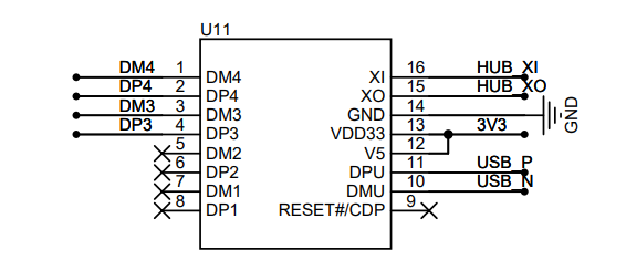
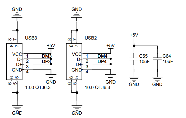
Figure 9 CH334R Schematic
⑩ Headphone Interface
The headphone interface uses the PJ-342 interface, with audio and recording:
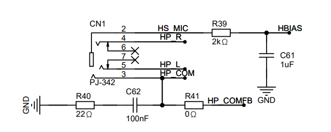
Figure 10 PJ-342 Headphone Interface
⑪ SD Card Interface
The SD card interface is used for inserting a MicroSD card.
R32-R36 are pull-up resistors for the SD card, here CLK does not need to be pulled up, otherwise it may affect SDIO communication.
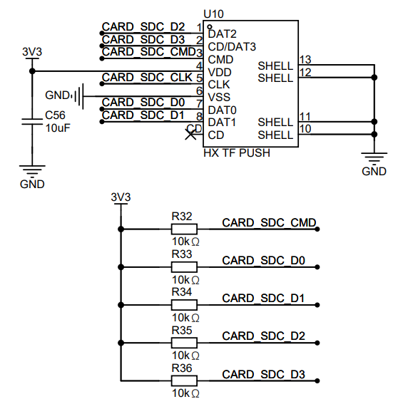
Figure 11 SD Card Interface
The software solution mainly discusses these8 parts
——Linux kernel, 2.4-inch LCD color screen driver, USB, Ethernet, wireless card RTL8723BS, ADC keys, audio playback, libcurl.
① Linux Kernel
② 2.4-inch LCD Color Screen Driver
The LCD color screen connects to the main control via SPI.
-
The software part uses TinyDRM, compared to the traditional fbtft, it no longer refreshes at a fixed frame rate. -
Uses DRM architecture, allowing for faster integration with new architecture programs.
Since the initialization code for screens varies by manufacturer, we only need to modify the code in the st7735r_pipe_enable function based on the original st7735r.c file.
The modified code can be referenced in the file below, the device tree configuration reference:
&spi0 {       status = "okay";       pinctrl-names = "default";       pinctrl-0 = <&spi0_pins>;

       display@0 {        compatible = "jianda,jd-t18003-t01";        reg = <0>;           spi-max-frequency = <95000000>;

        backlight = <&panel_backlight>;        dc-gpios = <&pio 4 9 0>; // PE9        reset-gpios = <&pio 4 8 0>; // PE8        rotation = <0>;    };};
In addition to SPI, a backlight node needs to be added, so that the backlight can be operated at the user level:
panel_backlight: panel-backlight { compatible = "gpio-backlight"; gpios = <&pio 4 7 GPIO_ACTIVE_HIGH>; // PE7 default-on; status = "okay"; };③ USB
The device tree configuration reference:
&usb_otg {       dr_mode = "host"; // peripheral       status = "okay"};

&usbphy {       status = "okay"};
In addition to the referenced nodes, ochi/echi must be added, otherwise USB insertion will have no response:
soc { ehci0: usb@01c1a000 { compatible = "allwinner,sun8i-v3s-ehci", "generic-ehci"; reg = <0x01c1a000 0x100>; interrupts = <GIC_SPI 72 IRQ_TYPE_LEVEL_HIGH>; clocks = <&ccu CLK_BUS_EHCI0>, <&ccu CLK_BUS_OHCI0>; resets = <&ccu RST_BUS_EHCI0>, <&ccu RST_BUS_OHCI0>; status = "okay"; };
ohci0: usb@01c1a400 { compatible = "allwinner,sun8i-v3s-ohci", "generic-ohci"; reg = <<|vq_15383|> <|vq_15384|> interrupts = <GIC_SPI 73 IRQ_TYPE_LEVEL_HIGH>; clocks = <&ccu CLK_BUS_EHCI0>, <&ccu CLK_BUS_OHCI0>, <&ccu CLK_USB_OHCI0>; resets = <&ccu RST_BUS_EHCI0>, <&ccu RST_BUS_OHCI0>; status = "okay"; }; };④ Ethernet
Directly reference the emac node from the DTSI file, the device tree reference:
&emac { allwinner,leds-active-low; status = "okay"};⑤ Wireless Card RTL8723BS
Under Linux, the SDIO architecture is similar to USB.
——After the device is inserted, if there is a corresponding driver, it will load automatically.
So in the device tree, we only need to configure the MMC1 interface, and then compile the corresponding driver ko, and load it into rootfs.
The device tree configuration reference is below:
&mmc1 { broken-cd; bus-width = <4>; vmmc-supply = <&reg_vcc3v3>; status = "okay"};The compiled ko file is under the overlay directory of buildroot, you can refer to the materials below:
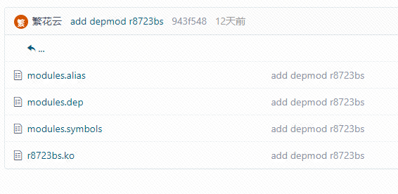
r8723bs.ko is the compiled kernel module, this module backports the driver from the 5.19 kernel, making it more stable compared to the 5.15 driver.
In addition to the ko file, you also need to load the network card firmware, refer to the directory below:
The rtl8723bs_nic.bin can be found on GitHub or other websites.
To connect to WiFi, refer to the script below:
[root@buildroot ~]# cat conn.shmodprobe r8723bs.kowpa_supplicant -B -i wlan0 -c /etc/wpa_supplicant.confudhcpc -i wlan0Refer to the configuration file below:
ctrl_interface=/var/run/wpa_supplicantap_scan=1

network={        ssid="###############"        psk="###############"}
⑥ ADC Keys
The test file has been open-sourced, no need to elaborate, if you want to use it directly, please refer to the open-source URL at the end.
⑦ Audio Playback
Buildroot integrates alsa, the default sound card is muted, open the terminal, input alsamixer, first unmute:
In the current interface, select Headphone, then press M to unmute, and use the keyboard ↑ to adjust the volume to an appropriate level. The interface can refer to Figure 12:
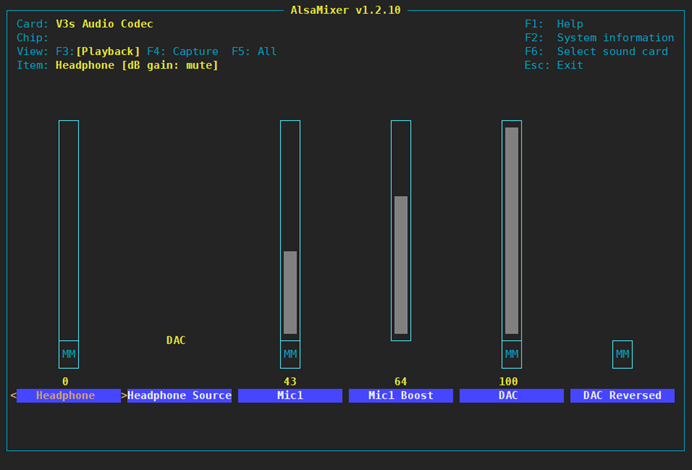
After adjustment, input mpv filename –no-video, insert headphones, and music playback can be achieved:
[root@buildroot ~]# mpv 2.flac --no-video     Video --vid=1 [P] (mjpeg 500x500 1.000fps) (+) Audio --aid=1 (flac 2ch 48000Hz)File tags: Album: 西厢寻他 Title: 西厢寻他 Track: 1AO: [alsa] 48000Hz stereo 2ch s32A: 00:00:04 / 00:03:43 (2%)

Exiting... (Quit)
Command prompt displays the current directory.
Edit the /etc/profile file and add a line:
export PS1='[
@h
]$ '
Then export /etc/profile to reload the configuration.
⑧ libcurl
Use libcurl to get the current weather. The program has been open-sourced, see the open-source URL at the end.
For 【project source files + video demonstration files】, please “scan” or “copy the link” to enter the open-source page.

Copy the open-source URL and open it in any browser: https://oshwhub.com/fanhuacloud/v3s_lcd
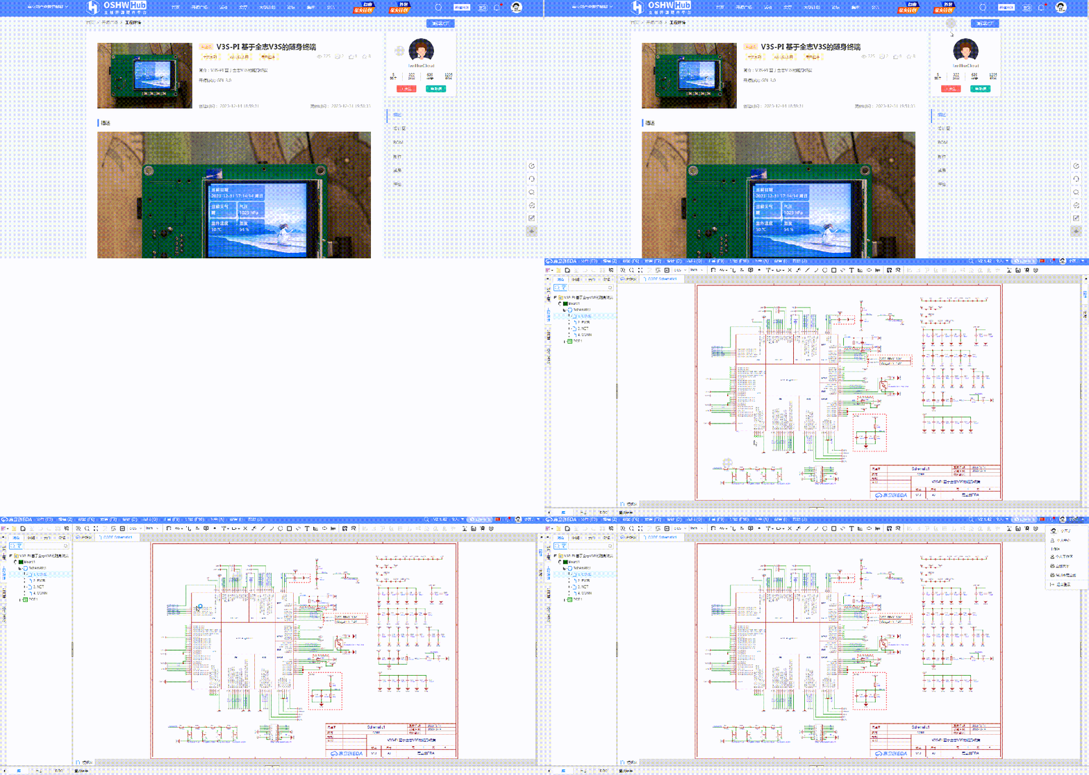
If you have any questions, you can comment and consult the original author under the open-source project!

*This article is a reprint of user creation from the “Lichuang Open Source Hardware Platform”. If there is any infringement, please contact for deletion.