2. Motors
2.1 MG 996R
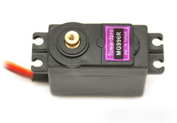
MG996R is a type of servo motor with three ports: power port, signal port, and ground port. The power port is used to connect to the power supply, the signal port is used to receive control signals (PWM), and the ground port is used for grounding. The signal port is used to receive control signals. When the duty cycle of the control signal is 0%, the servo turns to the far left; when the duty cycle is 100%, the servo turns to the far right; when the duty cycle is 50%, the servo turns to the middle position. The color of the ground port wire for MG996R is brown, the power port wire is red, and the signal port wire is orange.
2.2 Japan Nidec 12-24V Micro DC Brushless Servo Motor with AB Dual Channel 100 Line Encoder
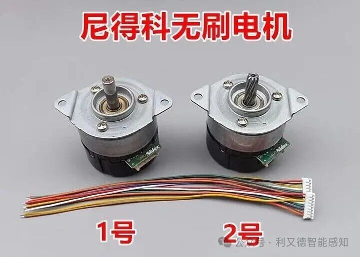
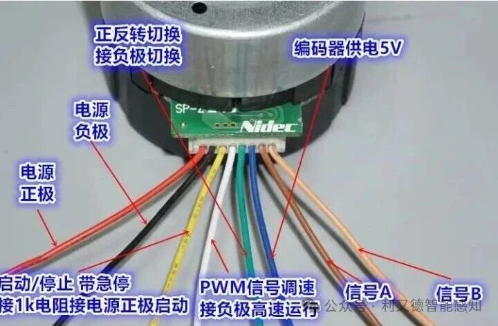
Encoder:
AB dual-channel 100-line encoder: An encoder is a device used to measure rotational angle, linear displacement, or speed. The AB dual-channel encoder is a common type of encoder that can output two orthogonal square wave signals to measure rotational angle and direction. A 100-line encoder means there are 100 pulses per rotation cycle.
Ports:
-
Line 1: Motor positive
-
Line 2: Motor negative
-
Line 3: Encoder A signal
-
Line 4: Encoder B signal
-
Line 5: Encoder Z signal
-
Line 6: Encoder power positive
-
Line 7: Encoder power negative
-
Line 8: Emergency stop signal 1
2.3 Hollow Cup Motors
2.3.1 614 Hollow Cup
Dimensions:
-
Leaf: 4.6cm = 46mm
-
Motor diameter: 6mm (3D printing suggests inner ring 6.3mm, thickness 3~5mm)
-
Motor height: 14mm
-
Axis diameter: 0.8mm
-
Output shaft length: 5mm
-
Weight: 2.5g
-
Rated voltage: 3.7V
-
No-load speed: 50000 RPM
-
No-load current: 0.15A
-
Stall torque: 0.05 N·m
-
Stall current: 1.8A
2.3.2 615 Hollow Cup
-
Motor diameter: 6mm
-
Motor length: 15mm
-
Output shaft diameter: 0.8mm
-
Output shaft length: 5mm
-
Weight: 2.5g
-
Rated voltage: 3.0V or 3.7V
-
No-load speed: 12000-65500 RPM
-
No-load current: 10-100mA
-
Stall torque: 0.33-16.95mN·m
-
Stall current: 160-3550mA
2.3.3 716 Hollow Cup
-
Motor diameter: 7mm
-
Motor length: 16mm
-
Output shaft diameter: 0.8mm or 1.0mm
-
Output shaft length: 4.5mm
-
Weight: 2.5g
-
Rated voltage: 3.0V or 3.7V
-
No-load speed: 12000-65500 RPM
-
No-load current: 10-100mA
-
Stall torque: 0.33-16.95mN·m
-
Stall current: 160-3550mA
2.3.4 720 Hollow Cup
-
Motor diameter: 7mm
-
Motor length: 20mm
-
Output shaft diameter: 1.0mm
-
Output shaft length: 4.5mm
-
Weight: 3g
-
Rated voltage: 3.0V or 3.7V
-
No-load speed: 12000-65500 RPM
-
No-load current: 10-100mA
-
Stall torque: 0.33-16.95mN·m
-
Stall current: 160-3550mA
2.3.5 816 Hollow Cup
-
Motor diameter: 8mm
-
Motor length: 16mm
-
Output shaft diameter: 1.0mm
-
Output shaft length: 4.5mm
-
Weight: 3.1g
-
Rated voltage: 3.4V or 6V
-
No-load speed: 24300-43000 RPM
-
No-load current: 60-142mA
-
Stall torque: 1.4-1.6mN·m
-
Stall current: 1180-6900mA
2.3.6 820 Hollow Cup
-
Motor diameter: 8.5mm
-
Motor length: 20mm
-
Output shaft diameter: 1.0mm
-
Output shaft length: 4.5mm
-
Weight: 3.5g
-
Rated voltage: 3.0V
-
No-load speed: 37500 RPM
-
No-load current: 100mA
-
Stall torque: 2.8mN·m
-
Stall current: 2.8A
2.3.7 8520 Hollow Cup
Dimensions
-
Motor diameter: 8.5mm
-
Motor length: 20mm
-
Output shaft diameter: 0.8mm
-
Output shaft length: 5mm
-
Weight: 2.5g
-
Rated voltage: 3.0V
-
No-load speed: 37500 RPM
-
No-load current: 0.15A
-
Stall torque: 0.05N·m
-
Stall current: 1.8A
2.3.8 1020 Hollow Cup
-
Motor diameter: 10mm
-
Motor length: 20mm
-
Output shaft diameter: 1.0mm
-
Output shaft length: 5.0mm
-
Weight: 4.5g
-
Rated voltage: 3.7V
-
No-load speed: 24500 RPM
-
No-load current: 120mA
-
Stall torque: 3.2mN·m
-
Stall current: 3.2A
3. Chips
3.1 Control Chips
3.1.1 STM32F103Z8T6
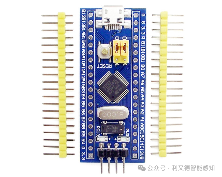
The following is the pin function allocation for STM32F103Z8T6:
-
PA0~PA7: 8-bit general IO ports
-
PB0~PB1: 2-bit general IO ports
-
PB3~PB5: 3-bit general IO ports
-
PB6~PB7: 2-bit general IO ports
-
PC13~PC15: 3-bit general IO ports
-
PB8~PB9: 2-bit general IO ports
-
PA8~PA11: 4-channel analog inputs
-
PA12: USB interface data line D+
-
PA13: USB interface data line D-
-
PA14: System clock output
-
PA15: System clock input
—————————————————-
-
SWIO and SWCLK are the debugging interfaces of STM32F103Z8T6
-
SWIO is the data line of the debugging interface,
-
SWCLK is the clock line of the debugging interface
—————————————————-
G port is a general input/output port
R port is a multiplexed input/output port
VB port is the multiplexed input/output port of STM32F103Z8T6
3.1.2 ESP-32
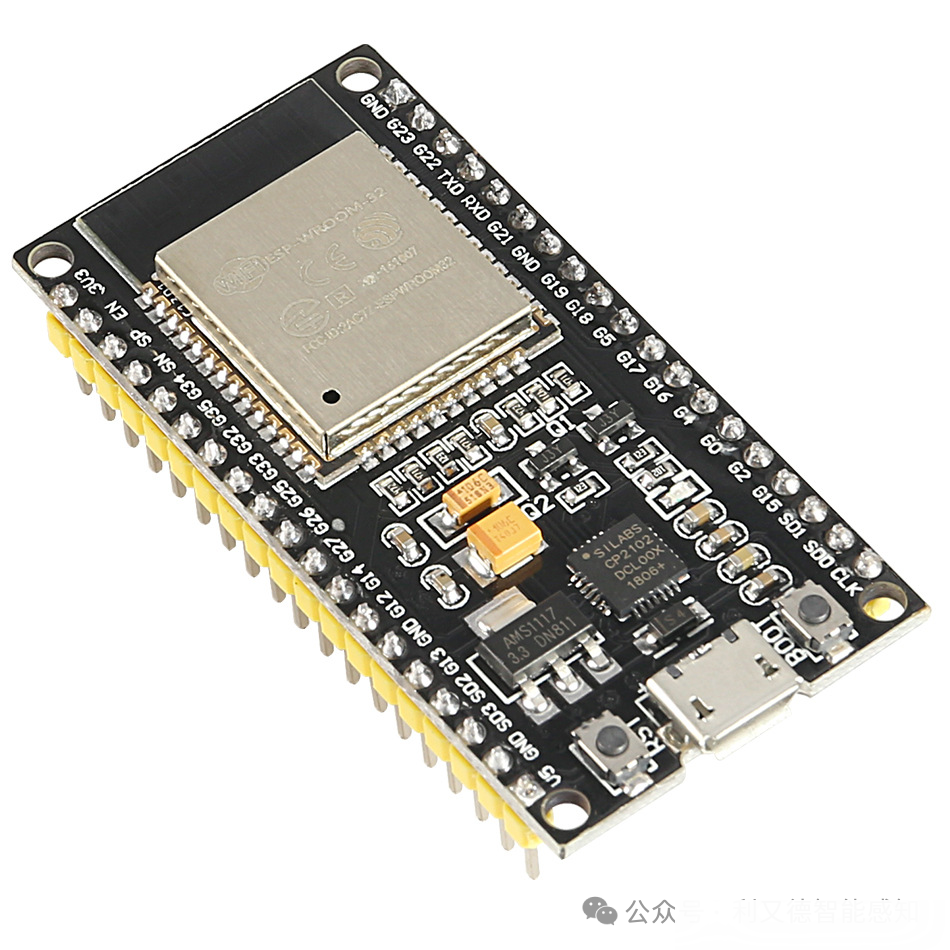
The ESP-32 pins refer to the 48 pins on the ESP-32 chip, which have various functions for connecting external devices and sensors. The ESP-32 pins can be categorized as follows:
-
Input-only pins: GPIO 34 to 39, with no internal pull-up or pull-down resistors, cannot be used as outputs.
-
SPI Flash pins: GPIO 6 to 11, connected to the integrated SPI flash on the ESP-WROOM-32 chip, not recommended for other uses.
-
Capacitive touch pins: GPIO 4, 0, 2, 15, 13, 12, 14, 27, 33, 32, can sense changes in charged substances, used to replace mechanical buttons or wake up the ESP-32.
-
Analog-to-Digital Converter (ADC) pins: GPIO 36, 37, 38, 39, 32, 33, 34, 35, 4, 0, 2, 15, 13, 12, 14, 27, 25, 26, can convert analog signals to digital signals with 12-bit resolution. Note that ADC2 pins (GPIO4 to 27) cannot be used when using Wi-Fi.
-
Digital-to-Analog Converter (DAC) pins: GPIO25 and 26, can convert digital signals to analog voltage signals output with 8-bit resolution.
-
RTC GPIOs: GPIO36 to 39 and 25 to 27, can be used in deep sleep mode to wake the ESP-32 from deep sleep.
-
Pulse Width Modulation (PWM) pins: All pins that can be used as outputs can be used as PWM pins (except GPIOs 34 to 39), used to generate PWM signals with different characteristics.
-
I2C pins: Any pin can be set as SDA or SCL, but by default, GPIO21 (SDA) and GPIO22 (SCL).
-
SPI pins: Any pin can be set as MOSI, MISO, CLK, or CS, but by default, GPIO23 (MOSI), GPIO19 (MISO), GPIO18 (CLK), and GPIO5 (CS).
-
Interrupt pins: All GPIOs can be configured as interrupts.
-
Strapping pins: GPIO0, 2, 4, 5, 12, and 15, used to put the ESP-32 into bootloader or programming mode. Care should be taken when using these pins as they may have unexpected behavior at startup.
3.1.3 Raspberry Pi Pico
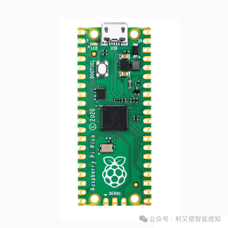
The Raspberry Pi Pico is a development board based on the RP2040 microcontroller, featuring 40 pins, of which 26 are GPIO pins that can be used for digital input/output, PWM, I2C, SPI, UART, and other functions.
The pins and their functions of the Raspberry Pi Pico are shown in the following table:
Pin Number Name Function
1. VBUS: 5V power from the micro-USB interface
2. VSYS: Main system input voltage, ranging from 1.8V to 5.5V
3. GND: Ground
4. 3V3_EN: Onboard SMPS chip enable
5. GP0 GPIO0: Can be used for UART0 TX, SPI0 RX, PWM A0, etc.
6. GP1 GPIO1: Can be used for UART0 RX, SPI0 CSn, PWM A1, etc.
7. GND: Ground
8. GP2 GPIO2: Can be used for I2C0 SDA, SPI0 SCK, PWM A2, etc.
9. GP3 GPIO3: Can be used for I2C0 SCL, SPI0 TX, PWM A3, etc.
10. GP4 GPIO4: Can be used for SPI0 CSn, PWM B0, etc.
11. GP5 GPIO5: Can be used for UART1 TX, SPI0 RX, PWM B1, etc.
12. GND: Ground
13. GP6 GPIO6: Can be used for UART1 RX, SPI0 CSn, PWM B2, etc.
14. GP7 GPIO7: Can be used for I2C1 SDA, SPI0 SCK, PWM B3, etc.
15. GP8 GPIO8: Can be used for I2C1 SCL, SPI0 TX, etc.
16. GP9 GPIO9: Can be used for SPI0 RX, etc.
17. GND: Ground
18. GP10 GPIO10: Can be used for SPI0 CSn, etc.
19. GP11 GPIO11: Can be used for SPI0 SCK, etc.
20. GP12 GPIO12: Can be used for SPI0 TX, etc.
21. GND: Ground
22. GP13 GPIO13: Can be used for SPI0 RX, etc.
23. GP14 GPIO14: Can be used for UART0 TX, etc.
24. GP15 GPIO15: Can be used for UART0 RX, etc.
25. GND: Ground
26. GP16 GPIO16: Can be used for UART1 TX, etc.
27. GP17 GPIO17: Can be used for UART1 RX, etc.
28-29. Empty (for internal use)
30-31. Empty (for internal use)
32-33. Empty (for internal use)
34-35. Empty (for internal use)
36-37. Empty (for internal use)
38-39. Empty (for internal use)
40-41. Empty (for internal use)
3.2 Driver Chips
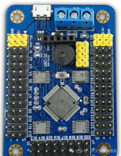
3.2.1 32-Channel Servo Control Board
The 32-channel servo control board is a circuit board that can control multiple servos simultaneously. It can communicate with a microcontroller or computer via serial or I2C interface, sending different commands to control the angle and speed of the servos.
The pins of the 32-channel servo control board have the following functions:
-
VCC: Input power positive, can connect to 5V or 6V power supply.
-
GND: Input power negative, connected to the power ground.
-
SCL: I2C clock line, used for I2C communication mode, connected to the SCL pin of the microcontroller or computer.
-
SDA: I2C data line, used for I2C communication mode, connected to the SDA pin of the microcontroller or computer.
-
TX: Serial transmission line, used for serial communication mode, connected to the RX pin of the microcontroller or computer.
-
RX: Serial reception line, used for serial communication mode, connected to the TX pin of the microcontroller or computer.
-
SEL: Communication mode selection line, used to select I2C or serial communication mode, connect to high level for I2C mode, connect to low level for serial mode.
-
ADDR: I2C address selection line, used to set the I2C communication address, can connect to high level, low level, or floating, corresponding to different addresses.
-
SERVO1~SERVO32: Servo output pins, corresponding to the signal lines of servos 1~32.
3.2.2 MX1919
MX1919 chip is a battery-powered motion control integrated brushed DC motor drive solution. It integrates a two-channel H-bridge drive circuit designed with N-channel and P-channel power MOSFETs, suitable for driving the steering wheels and rear wheels of electric toy cars.
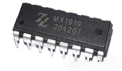
Pin Number Pin Name Pin Function
1. IN1: Controls the direction of output terminals OUT1 and OUT2
2. IN2: Controls the direction of output terminals OUT3 and OUT4
3. VCC: Chip power supply voltage, range from 2V to 9.6V
4. GND: Chip ground
5. OUT1: Motor output terminal, connects to OUT2 for one motor
6. OUT2: Motor output terminal, connects to OUT1 for one motor
7. GND: Chip ground
8. GND: Chip ground
9. GND: Chip ground
10. OUT3: Motor output terminal, connects to OUT4 for one motor
11. OUT4: Motor output terminal, connects to OUT3 for one motor
12. GND: Chip ground
13. VCC: Chip power supply voltage, range from 2V to 9.6V
14. IN3: Control enable signal for output terminals OUT1 and OUT2
15. IN4: Control enable signal for output terminals OUT3 and OUT4
16. NC: Not connected
3.5 CN3795
CN3795 is a PWM buck mode multi-cell battery charging management integrated circuit powered by solar panels, independently managing the charging of multiple cells, with advantages such as small package size, fewer external components, and simple usage. CN3795 has trickle, constant current, and constant voltage charging modes, making it very suitable for lithium batteries, lithium iron phosphate batteries, and lithium titanate batteries.
The pins and their functions of CN3795 are shown in the following table:
1. VG: Internal voltage regulator output. Provides power to the internal driving circuit, a 100nF capacitor needs to be connected between the VG pin and the VCC pin.
2. GND: Ground. Negative input of the input power and battery negative.
3. CHRG: Charging status indication pin. Open-drain output. In charging state, the internal transistor pulls this pin to low level; otherwise, this pin is in high impedance state.
4. MPPT: Solar panel maximum power point tracking pin. In the solar panel maximum power point tracking state, the voltage of this pin is modulated to 1.205V. This pin requires an external resistor divider network to detect the voltage of the solar panel.
5. COM: Loop compensation input pin. A 120Ω resistor and a 220nF capacitor need to be connected in series between this pin and ground.
6. FB: Battery voltage feedback input pin. External resistor divider network to detect battery voltage.
7. BAT: Battery positive connection pin and negative input for charging current detection. This pin connects to the positive terminal of the battery. This pin and the CSP pin are used to measure the voltage across the current detection resistor RCS and feedback this voltage signal to CN3795 for current modulation.
8. CSP: Charging current detection positive input pin. This pin and the BAT pin are used to measure the voltage across the current detection resistor RCS and feedback this voltage signal to CN3795 for current modulation.
9. VCC: External power positive input pin. VCC is also the power supply for the internal circuit. A filtering capacitor needs to be connected between this pin and ground.
10. DRV: Gate drive pin. Drives the gate of the external P-channel MOSFET.
3.3 Communication Chips
3.3.1 RF2520A
RF2520A is a 2.4 GHz ZigBee/IEEE 802.15.4 wireless transceiver produced by TI.
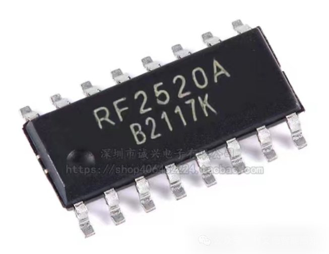
It has 16 pins, which are:
-
VDD: Power pin, provides voltage from 1.8V to 3.6V
-
GND: Ground pin
-
AVDD: Analog power pin, provides voltage from 1.8V to 3.6V
-
AGND: Analog ground pin
-
RSTn: Reset pin, active low
-
CSn: Chip select pin, active low
-
SI: Serial data input pin
-
SO: Serial data output pin
-
SCLK: Serial clock input pin
-
GPIO0-GPIO5: General input/output pins, configurable for different functions such as interrupt, modulation, demodulation, etc.
-
RF_P: RF differential output positive pin
-
RF_N: RF differential output negative pin
3.4 Flight Control Boards
3.4.1 CC3D Flight Control Board
Basic Introduction
-
Chip: The CC3D flight control uses an STM32F103CBT6 chip as the main control chip, responsible for attitude processing and providing signal output to the motors. This is a 32-bit ARM Cortex-M3 core microcontroller with a main frequency of 72MHz.
-
Sensors: The CC3D flight control uses an MPU-6000 as the attitude sensor, measuring the attitude state of the aircraft, which is analyzed and processed by the processor. This is a chip that integrates a three-axis gyroscope and a three-axis accelerometer, supporting I2C and SPI interfaces.
-
Serial Ports: The CC3D flight control has two serial ports, namely Main Port and Flexi Port. The Main Port can be used to connect to GPS modules or remote control receivers. The Flexi Port can be used to connect to remote control receivers or external sensors.
-
Input/Output: The CC3D flight control has six PWM output channels, which can be used to drive motors or servos for quadcopters, hexacopters, or fixed-wing aircraft. The CC3D flight control also has an RC input channel for receiving remote control signals.
-
Voltage Detection: The CC3D flight control does not have a built-in voltage detection function and requires an external module to achieve this. One method is to use a voltage divider resistor connected to the ADC pin of the Flexi Port, and then set the corresponding parameters in the ground station software. Another method is to use an electronic speed controller (ESC) with voltage detection functionality or a power distribution board, and then communicate with the CC3D flight control via serial or I2C interface.
-
OSD: The CC3D flight control does not have a built-in OSD (On Screen Display) function and requires an external module to achieve this. One method is to use a camera or video transmitter with OSD functionality, and then communicate with the CC3D flight control via serial or I2C interface.
-
Another method is to use a standalone OSD module, and connect it to the camera and video transmitter via video cables.
Other Features
-
The CC3D flight control is a two-layer circuit board with fewer components, making it cost-effective to manufacture.
-
The CC3D flight control supports various firmware such as OpenPilot/LibrePilot, CleanFlight/BetaFlight, allowing users to choose different firmware for flashing based on their needs.
-
The CC3D flight control supports multiple flight modes such as Rate, Attitude, AxisLock, Manual, allowing users to select different flight modes based on their skill level.
Disadvantages
-
The CC3D flight control is an earlier F1 flight controller, and its performance and functionality are inferior compared to later F3, F4, F7 flight controllers.
-
The CC3D flight control does not have built-in modules such as barometers, storage cards, GPS, airspeed meters, current meters, or optical flow sensors, which need to be achieved through external modules, increasing costs and weight, and occupying serial or I2C interfaces.
-
The CC3D flight control does not have a built-in co-processor, making it unable to implement advanced functions such as attitude estimation, navigation control, and task planning.
-
The CC3D flight control does not have a built-in PMU (Power Management Unit), making it unable to implement power management and protection functions, which need to be achieved through external modules.
-
The CC3D flight control does not have a built-in D-Bus interface, making it unable to perform high-speed data transmission with other devices.
Flashing and Simulation
-
The CC3D flight control can be flashed via USB or SWD interface. The USB interface requires the installation of corresponding drivers and flashing software, such as Zadig and Flash Loader Demonstrator. The SWD interface requires a JTAG or ST-LINK module to be connected to the SWCLK and SWDIO pins of the CC3D flight control.
-
The CC3D flight control can be simulated through ground station software such as OpenPilot GCS, LibrePilot GCS, etc. The ground station software can display the attitude, sensor data, output signals, etc., of the CC3D flight control, and can perform parameter settings and calibrations.
-
The CC3D flight control can be programmed by writing software using tools like Keil, Eclipse, etc. Programming software can modify the firmware source code of the CC3D flight control to implement custom functions and algorithms.
3.4.2 F4 Flight Control Board
Basic Introduction
-
Chip: The F4 flight control uses an STM32F405 chip as the main control chip, responsible for attitude processing and providing signal output to the motors. This is a 32-bit ARM Cortex-M4 core microcontroller with a main frequency of 168MHz.
-
Sensors: The F4 flight control typically uses an MPU6000 or ICM20602 as the attitude sensor, measuring the attitude state of the aircraft, which is analyzed and processed by the processor. These are chips that integrate a three-axis gyroscope and a three-axis accelerometer, supporting I2C and SPI interfaces. The F4 flight control can also connect external modules such as barometers, magnetometers, and GPS to achieve altitude holding, waypoint navigation, and return-to-launch functions.
-
Serial Ports: The F4 flight control has multiple serial ports, namely UART1~UART6. Different serial ports can be used to connect different devices, such as remote control receivers, OSD, GPS, and video transmission. The F4 flight control also supports receivers with protocols such as SBUS, IBUS, DSM, allowing multiple channels of signals to be received through one serial port.
-
Input/Output: The F4 flight control has multiple PWM output channels, which can be used to drive motors or servos for quadcopters, hexacopters, or fixed-wing aircraft. The F4 flight control also has a PPM input channel for receiving remote control signals. The F4 flight control also supports ESCs with DShot protocol for more precise motor control.
-
Voltage Detection: The F4 flight control has a built-in voltage detection function, which can be connected to the VBAT pin via a voltage divider resistor, and the corresponding parameters can be set in the ground station software. The F4 flight control can also communicate with ESCs or power distribution boards with voltage detection functionality via serial or I2C interface.
-
OSD: The F4 flight control has a built-in OSD (On Screen Display) function, which can display important information such as battery voltage, signal strength, flight time, flight mode, etc., on the video feed. The F4 flight control can also communicate with cameras or video transmitters with OSD functionality via serial or I2C interface.
Other Features
-
The F4 flight control is a newer flight controller, with improved performance and functionality compared to earlier F1 and F3 flight controllers.
-
The F4 flight control supports various firmware such as BetaFlight, INAV, PX4, allowing users to choose different firmware for flashing based on their needs.
-
The F4 flight control supports multiple flight modes such as Rate, Angle, Horizon, Air Mode, allowing users to select different flight modes based on their skill level.
-
The F4 flight control supports various ground station software such as BetaFlight Configurator, INAV Configurator, QGroundControl, allowing users to choose different ground station software for parameter tuning based on their firmware.
Disadvantages
-
The F4 flight control does not have a built-in inverter, making it unable to directly support SBUS protocol receivers, which need to be achieved through external modules or firmware modifications.
-
The F4 flight control does not have a built-in co-processor, making it unable to implement advanced functions such as attitude estimation, navigation control, and task planning.
-
The F4 flight control does not have a built-in PMU (Power Management Unit), making it unable to implement power management and protection functions, which need to be achieved through external modules.
-
The F4 flight control does not have a built-in D-Bus interface, making it unable to perform high-speed data transmission with other devices.
Flashing and Simulation
-
The F4 flight control can be flashed via USB or SWD interface. The USB interface requires the installation of corresponding drivers and flashing software, such as Zadig and Flash Loader Demonstrator. The SWD interface requires a JTAG or ST-LINK module to be connected to the SWCLK and SWDIO pins of the F4 flight control.
-
The F4 flight control can be simulated through ground station software such as BetaFlight Configurator, INAV Configurator, QGroundControl, etc. The ground station software can display the attitude, sensor data, output signals, etc., of the F4 flight control, and can perform parameter settings and calibrations.
-
The F4 flight control can be programmed by writing software using tools like Keil, Eclipse, etc. Programming software can modify the firmware source code of the F4 flight control to implement custom functions and algorithms.
3.4.3 APM Flight Control Board
Basic Introduction
-
Chip: The APM flight control uses an ATmega2560 chip as the main control chip, responsible for attitude processing and providing signal output to the motors. This is an 8-bit AVR core microcontroller with a main frequency of 16MHz.
-
Sensors: The APM flight control uses an MPU6000 as the attitude sensor, measuring the attitude state of the aircraft, which is analyzed and processed by the processor. This is a chip that integrates a three-axis gyroscope and a three-axis accelerometer, supporting I2C and SPI interfaces. The APM flight control also uses an MS5611 as a barometer to measure altitude information. The APM flight control can also connect external modules such as magnetometers and GPS to achieve waypoint navigation and return-to-launch functions.
-
Serial Ports: The APM flight control has two serial ports, namely UART0 and UART1. UART0 is used for communication with ground station software, while UART1 is used to connect to GPS modules or other devices. The APM flight control also supports receivers with protocols such as PPM, PWM, SBUS, allowing multiple channels of signals to be received through one input channel.
-
Input/Output: The APM flight control has multiple PWM output channels, which can be used to drive motors or servos for quadcopters, hexacopters, or fixed-wing aircraft. The APM flight control also has a PPM input channel for receiving remote control signals. The APM flight control also supports ESCs with DShot protocol for more precise motor control.
-
Voltage Detection: The APM flight control has a built-in voltage detection function, which can be connected to the ADC pin via a voltage divider resistor, and the corresponding parameters can be set in the ground station software. The APM flight control can also communicate with ESCs or power distribution boards with voltage detection functionality via I2C interface.
-
OSD: The APM flight control does not have a built-in OSD (On Screen Display) function and requires an external module to achieve this. The OSD module can display important information such as battery voltage, signal strength, flight time, flight mode, etc., on the video feed. The APM flight control can also communicate with cameras or video transmitters with OSD functionality via serial or I2C interface.
Other Features
-
The APM flight control is an open-source flight control system, offering high customizability and ease of use, suitable for beginners.
-
The APM flight control supports various firmware such as ArduCopter, ArduPlane, ArduRover, allowing users to choose different firmware for flashing based on their needs.
-
The APM flight control supports multiple flight modes such as Stabilize, Loiter, Alt Hold, Return To Launch, Land, Follow Me, allowing users to select different flight modes based on their skill level.
-
The APM flight control supports various ground station software such as Mission Planner, APM Planner 2, QGroundControl, allowing users to choose different ground station software for parameter tuning based on their firmware.
Disadvantages
-
The APM flight control uses an 8-bit microcontroller, and its performance and functionality are inferior compared to newer 32-bit microcontrollers, making it unable to implement advanced functions such as attitude estimation, navigation control, and task planning.
-
The APM flight control does not have a built-in co-processor, making it unable to share the computational load of the main control chip, nor can it implement dual protection and redundancy designs.
-
The APM flight control does not have a built-in PMU (Power Management Unit), making it unable to implement power management and protection functions, which need to be achieved through external modules.
-
The APM flight control does not have a built-in D-Bus interface, making it unable to perform high-speed data transmission with other devices.
-
The APM flight control can be flashed via USB or ISP interface. The USB interface requires the installation of corresponding drivers and flashing software, such as Zadig and Arduino IDE. The ISP interface requires a JTAG or AVRISP mkII module to be connected to the 6-pin ISP interface of the APM flight control.
-
The APM flight control can be simulated through ground station software such as Mission Planner, APM Planner 2, QGroundControl, etc. The ground station software can display the attitude, sensor data, output signals, etc., of the APM flight control, and can perform parameter settings and calibrations.
-
The ground station software can display the attitude, sensor data, output signals, etc., of the APM flight control, and can perform parameter settings and calibrations.
-
The APM flight control can be programmed by writing software using tools like Arduino IDE, Eclipse, etc. Programming software can modify the firmware source code of the APM flight control to implement custom functions and algorithms.
3.4.4 PIXHAWK Flight Control Board
Basic Introduction
-
Chip: The PIXHAWK flight control uses an STM32F427 chip as the main control chip, responsible for attitude processing and providing signal output to the motors. This is a 32-bit ARM Cortex-M4 core microcontroller with a main frequency of 180MHz.
-
Sensors: The PIXHAWK flight control uses an ICM20602 as the attitude sensor, measuring the attitude state of the aircraft, which is analyzed and processed by the processor. This is a chip that integrates a three-axis gyroscope and a three-axis accelerometer, supporting I2C and SPI interfaces. The PIXHAWK flight control also uses an MS5611 as a barometer to measure altitude information. The PIXHAWK flight control can also connect external modules such as magnetometers and GPS to achieve waypoint navigation and return-to-launch functions.
-
Serial Ports: The PIXHAWK flight control has multiple serial ports, namely UART1~UART8. Different serial ports can be used to connect different devices, such as remote control receivers, OSD, GPS, and video transmission. The PIXHAWK flight control also supports receivers with protocols such as SBUS, IBUS, DSM, allowing multiple channels of signals to be received through one serial port.
-
Input/Output: The PIXHAWK flight control has multiple PWM output channels, which can be used to drive motors or servos for quadcopters, hexacopters, or fixed-wing aircraft. The PIXHAWK flight control also has a PPM input channel for receiving remote control signals. The PIXHAWK flight control also supports ESCs with DShot protocol for more precise motor control.
-
Voltage Detection: The PIXHAWK flight control has a built-in voltage detection function, which can be connected to the ADC pin via a voltage divider resistor, and the corresponding parameters can be set in the ground station software. The PIXHAWK flight control can also communicate with ESCs or power distribution boards with voltage detection functionality via I2C interface.
-
OSD: The PIXHAWK flight control does not have a built-in OSD (On Screen Display) function and requires an external module to achieve this. The OSD module can display important information such as battery voltage, signal strength, flight time, flight mode, etc., on the video feed. The PIXHAWK flight control can also communicate with cameras or video transmitters with OSD functionality via serial or I2C interface.
Other Features
-
The PIXHAWK flight control is an open-source flight control system, offering high performance and functionality, suitable for professional users.
-
The PIXHAWK flight control supports various firmware such as PX4, ArduPilot, allowing users to choose different firmware for flashing based on their needs.
-
The PIXHAWK flight control supports multiple flight modes such as Stabilize, Loiter, Alt Hold, Return To Launch, Land, Follow Me, allowing users to select different flight modes based on their skill level.
-
The PIXHAWK flight control supports various ground station software such as QGroundControl, Mission Planner, APM Planner 2, allowing users to choose different ground station software for parameter tuning based on their firmware.
Disadvantages
-
The PIXHAWK flight control does not have a built-in inverter, making it unable to directly support SBUS protocol receivers, which need to be achieved through external modules or firmware modifications.
-
The PIXHAWK flight control does not have a built-in co-processor, making it unable to implement advanced functions such as attitude estimation, navigation control, and task planning.
-
The PIXHAWK flight control does not have a built-in PMU (Power Management Unit), making it unable to implement power management and protection functions, which need to be achieved through external modules.
-
The PIXHAWK flight control does not have a built-in D-Bus interface, making it unable to perform high-speed data transmission with other devices.
Simulation and Flashing
-
The PIXHAWK flight control can be flashed via USB or SWD interface. The USB interface requires the installation of corresponding drivers and flashing software, such as QGroundControl. The SWD interface requires a JTAG or ST-LINK module to be connected to the SWCLK and SWDIO pins of the PIXHAWK flight control.
-
The PIXHAWK flight control can be simulated through ground station software such as QGroundControl, Mission Planner, APM Planner 2, etc. The ground station software can display the attitude, sensor data, output signals, etc., of the PIXHAWK flight control, and can perform parameter settings and calibrations.
-
The PIXHAWK flight control can be programmed by writing software using tools like Eclipse, Visual Studio Code, etc. Programming software can modify the firmware source code of the PIXHAWK flight control to implement custom functions and algorithms.
3.4.5 NAZA Flight Control Board
3.4.5.1 NAZA-M Lite Flight Control
Basic Introduction
-
Chip: The NAZA-M Lite flight control uses an STM32F103CBT6 chip as the main control chip, responsible for attitude processing and providing signal output to the motors. This is a 32-bit ARM Cortex-M3 core microcontroller with a main frequency of 72MHz.
-
Sensors: The NAZA-M Lite flight control uses an MPU6050 as the attitude sensor, measuring the attitude state of the aircraft, which is analyzed and processed by the processor. This is a chip that integrates a three-axis gyroscope and a three-axis accelerometer, supporting I2C interface. The NAZA-M Lite flight control also uses an MS5611 as a barometer to measure altitude information. The NAZA-M Lite flight control can also connect external modules such as magnetometers and GPS to achieve waypoint navigation and return-to-launch functions.
-
Serial Ports: The NAZA-M Lite flight control has one serial port, which can be used to connect to GPS modules or other devices. The NAZA-M Lite flight control also supports receivers with protocols such as PPM, SBUS, DSM, allowing multiple channels of signals to be received through one input channel.
-
Input/Output: The NAZA-M Lite flight control has multiple PWM output channels, which can be used to drive motors or servos for quadcopters, hexacopters, or fixed-wing aircraft. The NAZA-M Lite flight control also has a PPM input channel for receiving remote control signals. The NAZA-M Lite flight control also supports ESCs with DShot protocol for more precise motor control.
-
Voltage Detection: The NAZA-M Lite flight control does not have a built-in voltage detection function and requires an external module to achieve this. The external module can be connected to the ADC pin via a voltage divider resistor, and the corresponding parameters can be set in the ground station software. The NAZA-M Lite flight control can also communicate with ESCs or power distribution boards with voltage detection functionality via I2C interface.
-
OSD: The NAZA-M Lite flight control does not have a built-in OSD (On Screen Display) function and requires an external module to achieve this. The OSD module can display important information such as battery voltage, signal strength, flight time, flight mode, etc., on the video feed. The NAZA-M Lite flight control can also communicate with cameras or video transmitters with OSD functionality via serial or I2C interface.
3.4.5.2 NAZA-M V2
Basic Information
-
Chip: The NAZA-M V2 flight control uses an STM32F103CBT6 chip as the main control chip, responsible for attitude processing and providing signal output to the motors. This is a 32-bit ARM Cortex-M3 core microcontroller with a main frequency of 72MHz.
-
Sensors: The NAZA-M V2 flight control uses an MPU6050 as the attitude sensor, measuring the attitude state of the aircraft, which is analyzed and processed by the processor. This is a chip that integrates a three-axis gyroscope and a three-axis accelerometer, supporting I2C interface. The NAZA-M V2 flight control also uses an MS5611 as a barometer to measure altitude information. The NAZA-M V2 flight control can also connect external modules such as magnetometers and GPS to achieve waypoint navigation and return-to-launch functions.
-
Serial Ports: The NAZA-M V2 flight control has two serial ports, namely UART0 and UART1. UART0 is used for communication with ground station software, while UART1 is used to connect to GPS modules or other devices. The NAZA-M V2 flight control also supports receivers with protocols such as PPM, SBUS, DSM, allowing multiple channels of signals to be received through one input channel.
-
Input/Output: The NAZA-M V2 flight control has multiple PWM output channels, which can be used to drive motors or servos for quadcopters, hexacopters, or fixed-wing aircraft. The NAZA-M V2 flight control also has a PPM input channel for receiving remote control signals. The NAZA-M V2 flight control also supports ESCs with DShot protocol for more precise motor control.
-
Voltage Detection: The NAZA-M V2 flight control has a built-in voltage detection function, which can be connected to the ADC pin via a voltage divider resistor, and the corresponding parameters can be set in the ground station software. The NAZA-M V2 flight control can also communicate with ESCs or power distribution boards with voltage detection functionality via I2C interface.
-
OSD: The NAZA-M V2 flight control does not have a built-in OSD (On Screen Display) function and requires an external module to achieve this. The OSD module can display important information such as battery voltage, signal strength, flight time, flight mode, etc., on the video feed. The NAZA-M V2 flight control can also communicate with cameras or video transmitters with OSD functionality via serial or I2C interface.
3.4.5.3 NAZA-H
NAZA-H Introduction
-
Chip: The NAZA-H does not disclose the model and specifications of the chip, but it can be inferred to be a high-performance microcontroller used to process data from various sensors and execute flight control algorithms.
-
Sensors: The NAZA-H has a built-in 6-degree-of-freedom inertial measurement unit (IMU), including a gyroscope and accelerometer, used to measure the attitude and acceleration of the aircraft. The NAZA-H also has a built-in magnetometer for measuring the aircraft’s heading. The NAZA-H also has a built-in barometric altimeter for measuring the aircraft’s altitude. The NAZA-H supports external GPS modules for measuring the aircraft’s position and speed.
-
Serial Ports: The NAZA-H has two serial ports, one for connecting to GPS modules and one for connecting to a computer or remote control.
-
Input/Output: The NAZA-H has six input channels corresponding to the six channels of the remote control: throttle, aileron, elevator, rudder, mode switch, and stabilization switch. The NAZA-H has three output channels corresponding to the three servo motors of the helicopter: main rotor, tail rotor, and tail lock.
-
Voltage Detection: The NAZA-H has a built-in voltage detection function that can monitor the battery voltage of the aircraft in real-time and issue a warning signal when the voltage is low.
-
OSD: The NAZA-H does not have a built-in OSD (On Screen Display) function, but it can connect to third-party OSD devices, such as DJI iOSD Mark II, via the D-BUS interface to display various information about the aircraft.
-
Storage Card: The NAZA-H does not have built-in storage card functionality and does not support external storage card devices.
-
PWM: The NAZA-H uses PWM (Pulse Width Modulation) signals to control the angle and speed of the servo motors.
-
Redundancy Design: The NAZA-H does not explicitly state whether it has a redundancy design, but it can be inferred that it does not, as it only has one chip and one set of sensors, and if a failure occurs, it may not be recoverable.
-
Open Source: The NAZA-H has not open-sourced any code or hardware design; it is a proprietary flight control system developed and sold by DJI.
-
Airspeed Meter: The NAZA-H does not have built-in airspeed meter functionality and does not support external airspeed meter devices.
-
Current Meter: The NAZA-H does not have built-in current meter functionality and does not support external current meter devices.
-
Optical Flow Sensor: The NAZA-H does not have built-in optical flow sensor functionality and does not support external optical flow sensor devices.
-
Flight Modes: The NAZA-H supports three flight modes: manual mode, attitude mode, and GPS attitude mode. In manual mode, the pilot has full control over the aircraft’s attitude and position; in attitude mode, the NAZA-H automatically stabilizes the aircraft’s attitude and maintains level flight; in GPS attitude mode, the NAZA-H automatically stabilizes the aircraft’s attitude and maintains its position.
-
Open Source Ground Station: The NAZA-H does not have open-sourced ground station software; it only provides an official assistant software for connecting the computer and flight controller for parameter settings and firmware upgrades.
-
How to Simulate and Flash: The NAZA-H does not support post-programming of the board; it can only perform firmware upgrades through the assistant software and cannot customize or modify the firmware. To perform a firmware upgrade, the following steps are required:
-
– Download and install the NAZA-H assistant software and DJI WIN driver.
-
– Connect the NAZA-H flight controller to the computer and open the assistant software.
-
– Click the firmware upgrade button and select the firmware version to upgrade.
-
– Click the start upgrade button and wait for the upgrade to complete.
-
– Click the exit button, disconnect, and restart the flight controller.

Wuhan Li You De Technology Co., Ltd.
TEL: 027-83621617
13296589910